Power line communication device, power supply circuit with communication function, electric appliance, and control and monitoring system

Active Publication Date: 2015-09-15
SUMITOMO ELECTRIC IND LTD +1
View PDF22 Cites 0 Cited by
  • Summary
  • Abstract
  • Description
  • Claims
  • Application Information

AI Technical Summary

Benefits of technology

[0015](3) On the other hand, the present invention is a power supply circuit that performs an AC / DC conversion by switching based on an AC voltage supplied from a power line. The power supply circuit includes: a semiconductor switching element that performs the switching; a demodulator unit that extracts and demodulates a signal of power line communication that is transmitted using the power line as a signal transmission path; and a modulator unit that uses an unoccupied time of switching for the AC / DC conversion to control ON / OFF operations of the semiconductor switching element, to thereby cause a communication signal of a modulated rectangular wave to be output to the power line for a prescribed period.
[0016]With the power supply circuit with the communication function structured as above, by switching the semiconductor switching element in the ON / OFF operation mode having undergone the phase modulation based on a signal of the power line communication to be transmitted, a signal of the power line communication can be transmitted via the power line. Accordingly, a line driver or a high frequency transformer for sending a signal of the power line communication on the power line is not required. Further, use of the power supply circuit eliminates the necessity of parallel use of a power supply unit dedicated to the power line communication function. Still further, the semiconductor switching element of the power supply circuit can be used.

Problems solved by technology

(2) Further, in the power line communication device, the semiconductor switching element may also be used for performing switching in a power supply circuit supplied with an AC voltage from the power line, and the modulator unit may cause the semiconductor switching element to output the communication signal in an unoccupied time not being occupied with a power signal from the power supply circuit.

Method used


Image

  • Power line communication device, power supply circuit with communication function, electric appliance, and control and monitoring system
  • Power line communication device, power supply circuit with communication function, electric appliance, and control and monitoring system
  • Power line communication device, power supply circuit with communication function, electric appliance, and control and monitoring system

Examples


Embodiment Construction

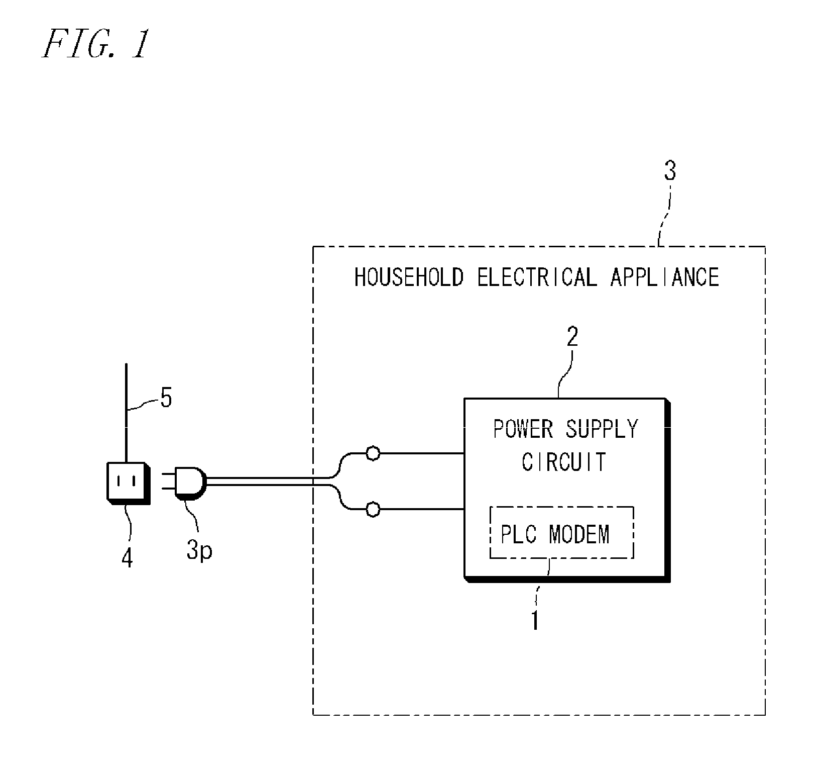
[0034]FIG. 1 is a diagram showing the schematic configuration of a power line communication device (hereinafter referred to as a PLC modem) and a power supply circuit with a communication function based on power line communication according to one embodiment of the present invention. That is, PLC modem 1 is installed in power supply circuit 2, and power supply circuit 2 is installed in household electrical appliance 3, for example. By plug 3p connected to the primary side of power supply circuit 2 being inserted into outlet 4, power supply circuit 2 is supplied with a commercial AC voltage (AC 100 V) from power line 5, and PLC modem 1 can perform the power line communication.

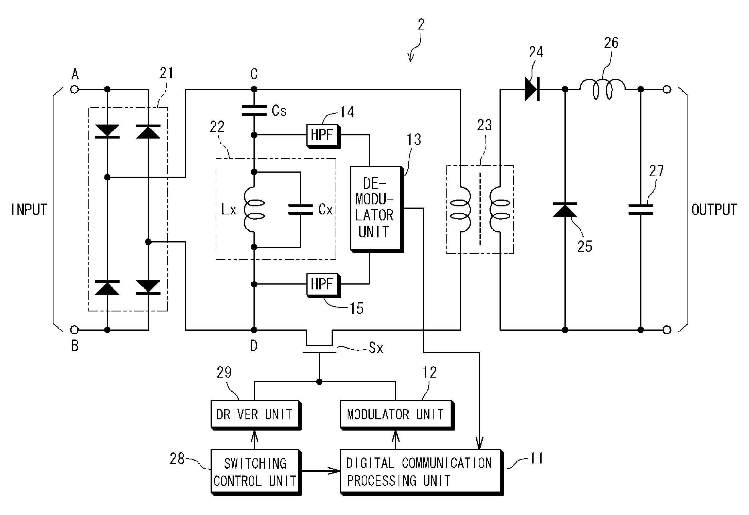
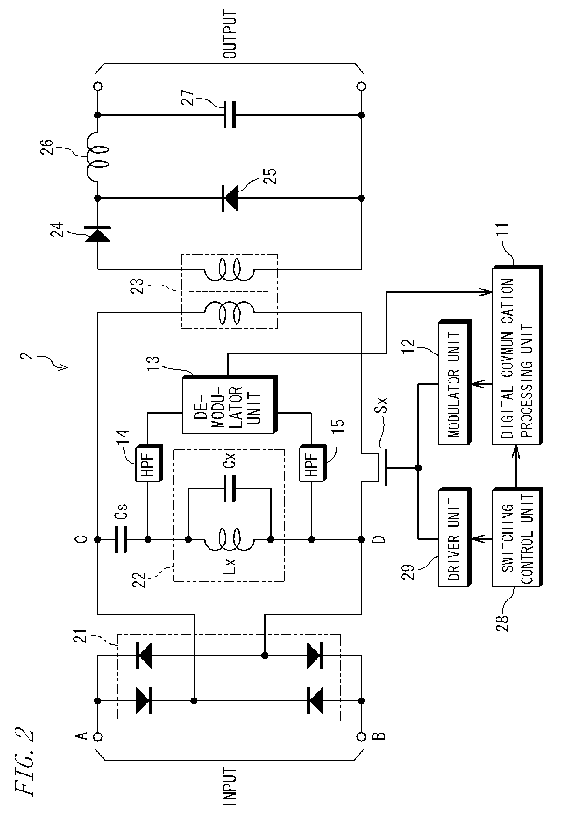
[0035]FIG. 2 is a circuit diagram showing the internal configuration of power supply circuit 2. Power supply circuit 2 uses the commercial AC voltage as the input voltage, and provides a prescribed DC output voltage (for example, DC 16 V) by performing rectification and AC / DC conversion by switching. Specificall...


PUM


Abstract

To realize a transmission function of power line communication by a further simplified and cost-effective circuit configuration, in a PLC modem installed in an electric appliance such as a household electrical appliance. A semiconductor switching element that is present on an electric circuit connected to a power line is driven by a modulator unit. The modulator unit controls ON/OFF operations of the semiconductor switching element, to thereby cause a communication signal of a modulated rectangular wave to be output to the power line for a prescribed period.

Description

RELATED APPLICATIONS[0001]This application is the U.S. National Phase under 35 U.S.C. §371 of International Application No. PCT / JP2010 / 063146, filed on Aug. 4, 2010, which in turn claims the benefit of Japanese Application No. 2009-183745, filed on Aug. 6, 2009, the disclosures of which Applications are incorporated by reference herein.TECHNICAL FIELD[0002]The present invention relates to a power line communication device that uses a power line as a signal transmission path, a power supply circuit having installed therein a function of power line communication, an electric appliance, and a control and monitoring system.BACKGROUND ART[0003]The technique of structuring a network in a home area by the power line communication (PLC: Power Line Communication) is already in practical use. Such power line communication makes it possible to establish communication between PLC modems (power line communication devices) each connected to an outlet, in which a power line (domestic wiring) is us...

Claims


Application Information

Patent Timeline
Patent Type & Authority Patents(United States)
IPC IPC(8): G08C19/12H04B3/56H04B3/54
CPCH04B3/56H04B3/54H04B2203/547H04B2203/5458H04B2203/5416
Inventor HIKIHARA, TAKASHITAKUNO, TSUGUHIROHIROTSU, KENICHISHIMOGUCHI, TAKEFUMISHIBATA, TOSHIKAZUTSUNO, TAKASHIHATSUKAWA, SATOSHI
Owner SUMITOMO ELECTRIC IND LTD
Why Eureka
Try Eureka