Fishing rod caddy

Inactive Publication Date: 2015-09-22
GROVES JR JACK R +1
View PDF30 Cites 13 Cited by
  • Summary
  • Abstract
  • Description
  • Claims
  • Application Information

AI Technical Summary

Benefits of technology

[0012]It is another object of the present invention to provide a fishing rod caddy which is easily transportable. Design features allowing this object to be accomplished include a fishing caddy manufactured of light-weight material, a top and bottom joined by columns, lightening holes/drains in the bottom, and built-in caddy handles. Benefits associated with the accomplishment of this object include ease of transportation and storage of the fishing rod caddy.
[0013]It is still another object of this invention to provide a fishing rod caddy which does not absorb or retain water. Design features enabling the accomplishment of this object include a fishing rod caddy made of non-absorptive material. Advantages associated with the realization of this object include quick caddy drying after fishing rod rinsing, and avoidance of mold growing on the fishing rod caddy.
[0014]It is another object of the present invention to provide a fishing rod caddy which accommodates storage and transportation of tackle box trays. Design features allowing this object to be accomplished include fins extending into the top mouth and caddy cavity, which define slots sized to slidably admit a tackle box tray. A benefit associated with the accomplishment of this object

Problems solved by technology

An on-going problem is the absence of an effective way to hold fishing rods in order to rinse them off with a hose, and subsequently to hold them while they dry.
Wood tends to hold water, which lengthens the fishing rod drying process.
While these taught fishing rod supports, the fact that the supports depended from containers used for other purposes rendered them inappropriate for use as fishing rod holders while rinsing of fishing rods with fresh water, because water and salt runoff from the fishing rods could enter and foul the interior of

Method used


Image

  • Fishing rod caddy
  • Fishing rod caddy
  • Fishing rod caddy

Examples


Example

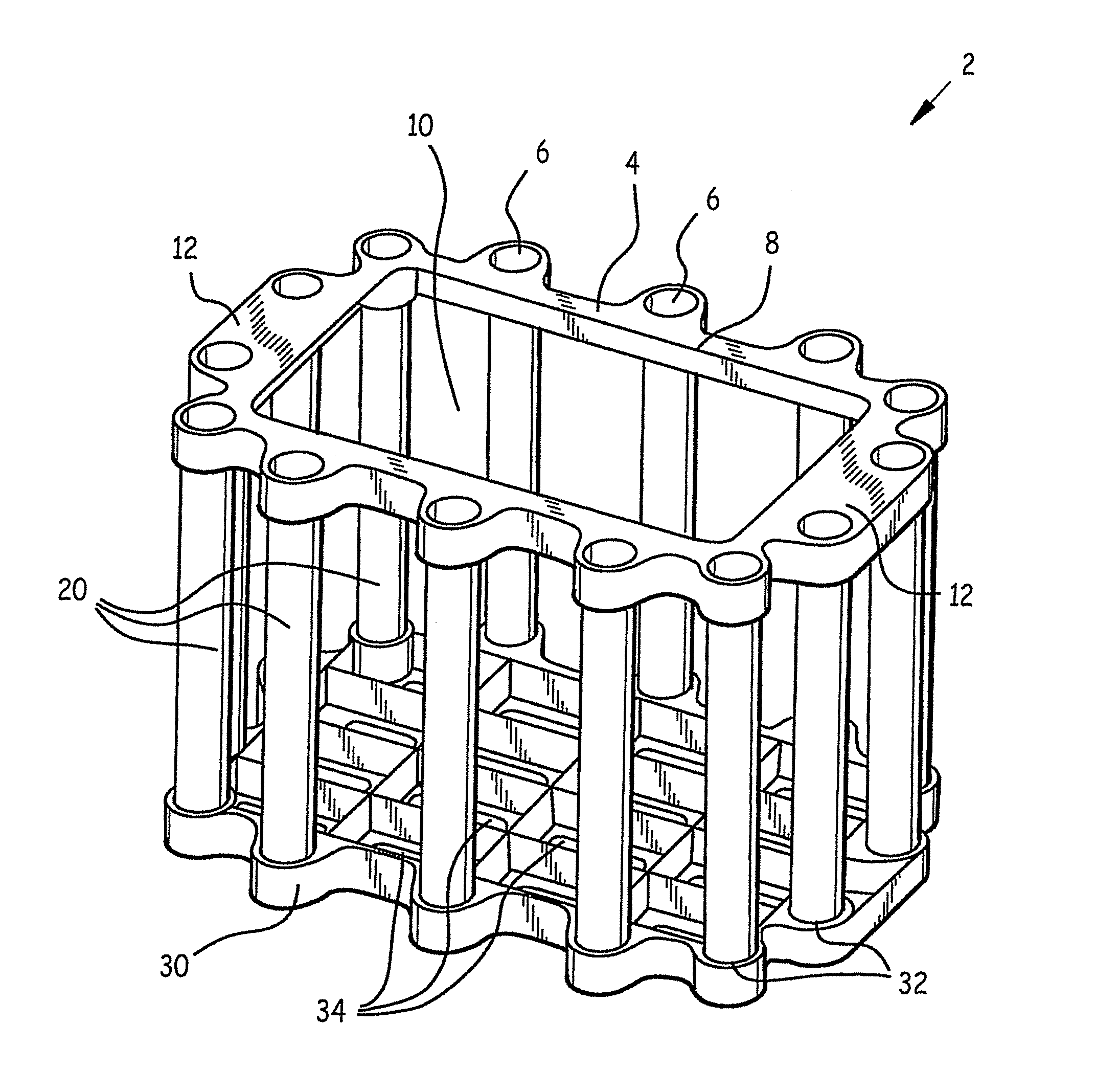
[0026]Referring now to FIG. 1, a front left quarter isometric view of fishing rod caddy 2, fishing rod caddy 2 is made up of three principal components: substantially planar top 6, elongate columns 20, and substantially planar bottom 30. Top 4 comprises a plurality of top receptacles 6 disposed around its perimeter, each sized to frictionally admit a corresponding column 20 upper end. Bottom 30 comprises a bottom receptacle 32 corresponding to, and disposed directly below, each top receptacle 6. Each bottom receptacle 32 is sized to frictionally admit a corresponding column 20 lower end. Bottom receptacles 32 are disposed around the perimeter of bottom 30.

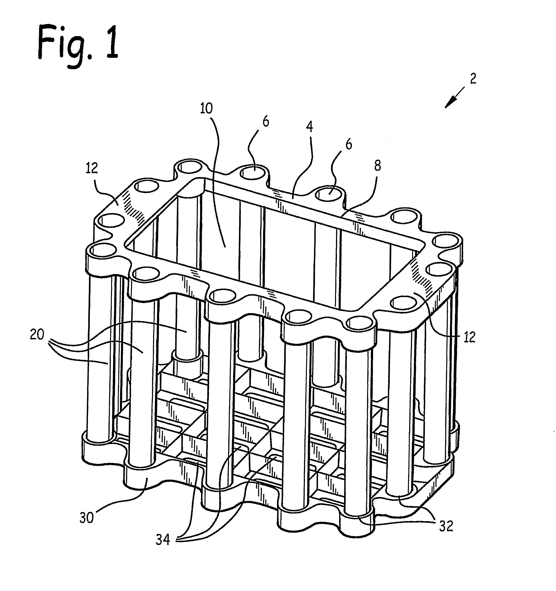
[0027]FIG. 2 is a front left quarter exploded isometric view of fishing rod caddy 2. FIG. 3 is a front cross-sectional view of fishing rod caddy 2. FIG. 3 is a front cross-sectional view of a fishing rod caddy 2. FIG. 4 is a top view of fishing rod caddy 2. Referring now to these figures, fishing caddy 2 is assembled by frictionall...


PUM


Abstract

A fishing rod cavity. A top is joined to a bottom by a plurality of columns. An upper end of each column is frictionally disposed within a top cavity; a lower end of each column is frictionally disposed within a bottom cavity. A column cavity sized to admit a fishing rod handle is disposed at an upper end of each column, to hold the fishing rod for rinsing after salt water use. Drains through the bottom allow rinse water to escape out of a cavity in the fishing rod caddy, and also reduce the fishing rod caddy's weight. Alternate embodiments provide slots sized to admit, store, and transport tackle box trays, and a cavity sized to admit a standard bucket. The fishing rod caddy is made of nylon, plastic, or synthetic material to reduce water absorption and help prevent mold growth on the fishing rod caddy.

Description

BACKGROUND OF THE INVENTION[0001]1. Field of the Invention[0002]This invention relates to fishing equipment, and in particular to a fishing rod caddy.[0003]2. Background of the Invention[0004]Rod fishing is a popular sport pursued by millions each year. After use in salt water, fishing rods must be rinsed in order to prevent corrosion by the salt. An on-going problem is the absence of an effective way to hold fishing rods in order to rinse them off with a hose, and subsequently to hold them while they dry. In addition, it would be desirable to provide an apparatus to store and transport the fishing rods between uses.[0005]Other considerations in the design of a rinse-off fishing rod holder are light weight (to make it easily transportable), and a material which is resistant to mold, such as nylon, plastic, or synthetic. Wood tends to hold water, which lengthens the fishing rod drying process. Built-in handles would also be useful to facilitate transportation.[0006]Finally, slots ins...

Claims


Application Information

Patent Timeline
IPC IPC(8): A47F7/00A01K97/08A01K97/10A47B81/00
CPCA47B81/005A01K97/08A01K97/10
Inventor GROVES, JR., JACK R.GROVES, NADINE M.
Owner GROVES JR JACK R
Why Eureka
Try Eureka