Drag reduction of a tractor trailer using guide vanes

a technology of tractor trailer and guide rod, which is applied in the field of tractor trailer, can solve the problems of large inconvenience of extending and collapsing the device on the back of the tractor trailer, heavy weight of current boat-tail and planar cavity design, etc., and achieves the effects of reducing weight and simplicity, reducing costs, and reducing labor intensity

Inactive Publication Date: 2015-09-22
CLARKSON UNIVERSITY
View PDF18 Cites 14 Cited by
  • Summary
  • Abstract
  • Description
  • Claims
  • Application Information

AI Technical Summary

Benefits of technology

[0024]It is therefore a principal object and an advantage of the present invention to provide a modular vaned design that can be an easy, one-time installation without ever having to expand or collapse the device. With this design, a truck driver's job can be made even easier since once the device is installed, no other manipulation is needed on his / her part.
[0025]It is another object and advantage of the present invention to provide a modular vaned design or guide vane system that can require roughly a third of the material that prior designs need. Reduced weight and simplicity most often translates into lower costs, and ease of manufacturability. A simpler vaned design as provided herein, can be just as effective as any other aft drag reduction designs, and can be very beneficial and easily marketable (e.g., fixed guide vanes of a much smaller size than current cavity devices).
[0026]In accordance with the above-referenced objects and advantages, an embodiment of the present invention is directed to a vehicle having an apparatus for reducing aerodynamic drag including, but not limited to: a vehicle having a front side, and an aft side located in a first plane with an aft perimeter, wherein the aft perimeter includes a first vertical surface, a second vertical surface, a first horizontal surface and a second horizontal surface; a guide vane with an airfoil cross-section having a leading edge and a trailing edge, wherein: the leading edge is bulbous and tapers to the trailing edge, the guide vane is mounted around and to the aft perimeter along a portion of at least one of the first vertical surface, the second vertical surface, the first horizontal surface and the second horizontal surface; and the leading edge faces and extends in a direction toward the front side beyond the first plane.
[0027]As further described in the Detailed Description Section below, the discovery that blunt body drag can be dramatically reduced using vanes has the potential to be revolutionary for tractor trailer aerodynamics. Also, all the referenced Clarkson studies serve as good precedents for how to go about investigating guide vanes as drag reduction devices. Building on this strong foundation of prior research at Clarkson, embodiments of the present invention seek to go in a slightly different direction with aft drag reduction devices. While previous research has focused on planar cavity concepts, there has been no venture into investigating how guide vanes may reduce drag (especially in tractor trailers). Using the wind tunnel techniques and background that these previous studies have provided, the current specification focuses specifically on guide vanes as an alternative form of drag reduction and their full size usability.

Problems solved by technology

While designs like TrailerTails®, for example, are finally becoming accessible to trucking firms, there is still a large degree of inconvenience involved in extending and collapsing the device on the back of the truck (where, for example, a truck driver has to fold and unfold the aerodynamic device).
Additionally, the current boat-tail and planar cavity designs are bulky, and can be heavy.

Method used


Image

  • Drag reduction of a tractor trailer using guide vanes
  • Drag reduction of a tractor trailer using guide vanes
  • Drag reduction of a tractor trailer using guide vanes

Examples


example 1

Computational Fluid Dynamic Analysis

[0071]This Example sets forth a description of the computational fluid dynamic (CFD”) analysis used to investigate the potential of drag reduction with arc-shaped vanes. Using the data from the initial wind tunnel testing in Japan as a starting point, a comprehensive CFD optimization study was initiated. The purpose of this study was to use relationships between boundary layer formation, thickness and the geometry of the vanes to ultimately find out the optimal geometry of the vanes. In this way, through continually optimizing the computer model, a good correlation between model geometry and drag reduction could be obtained.

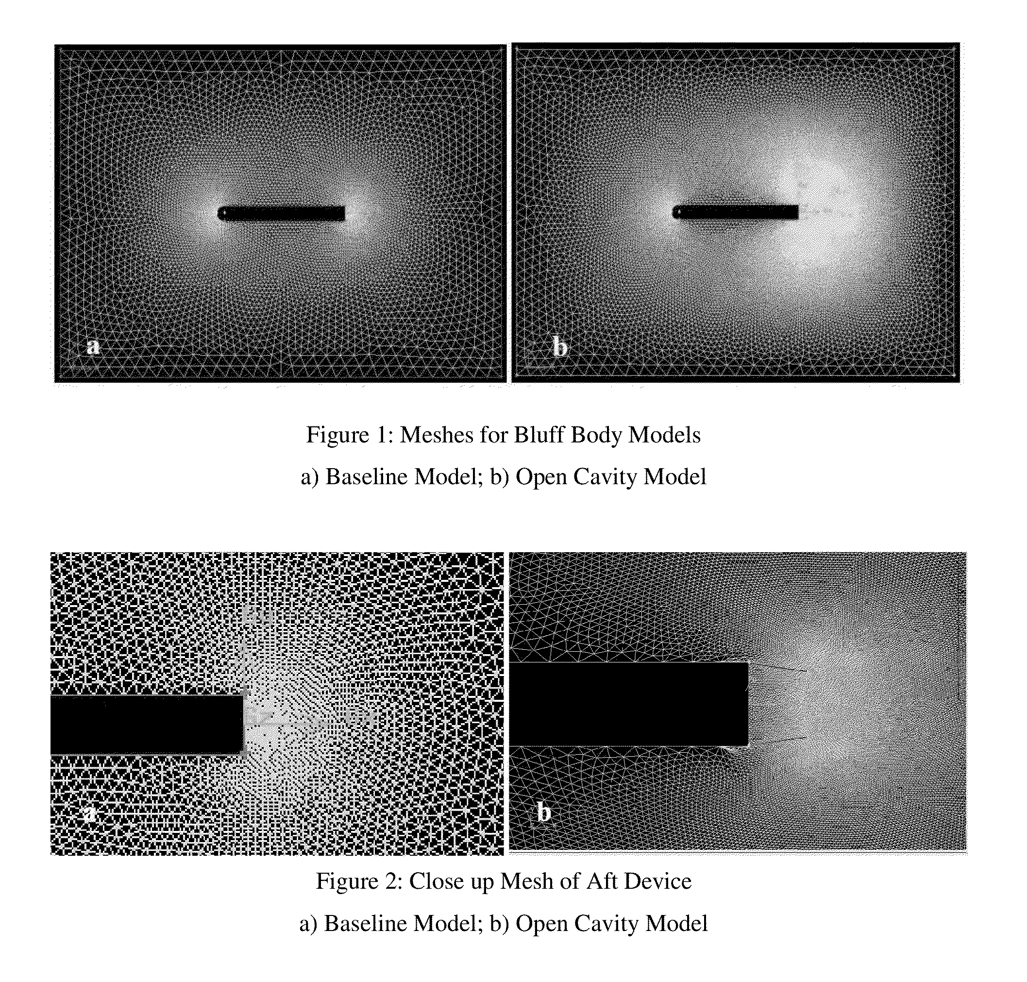
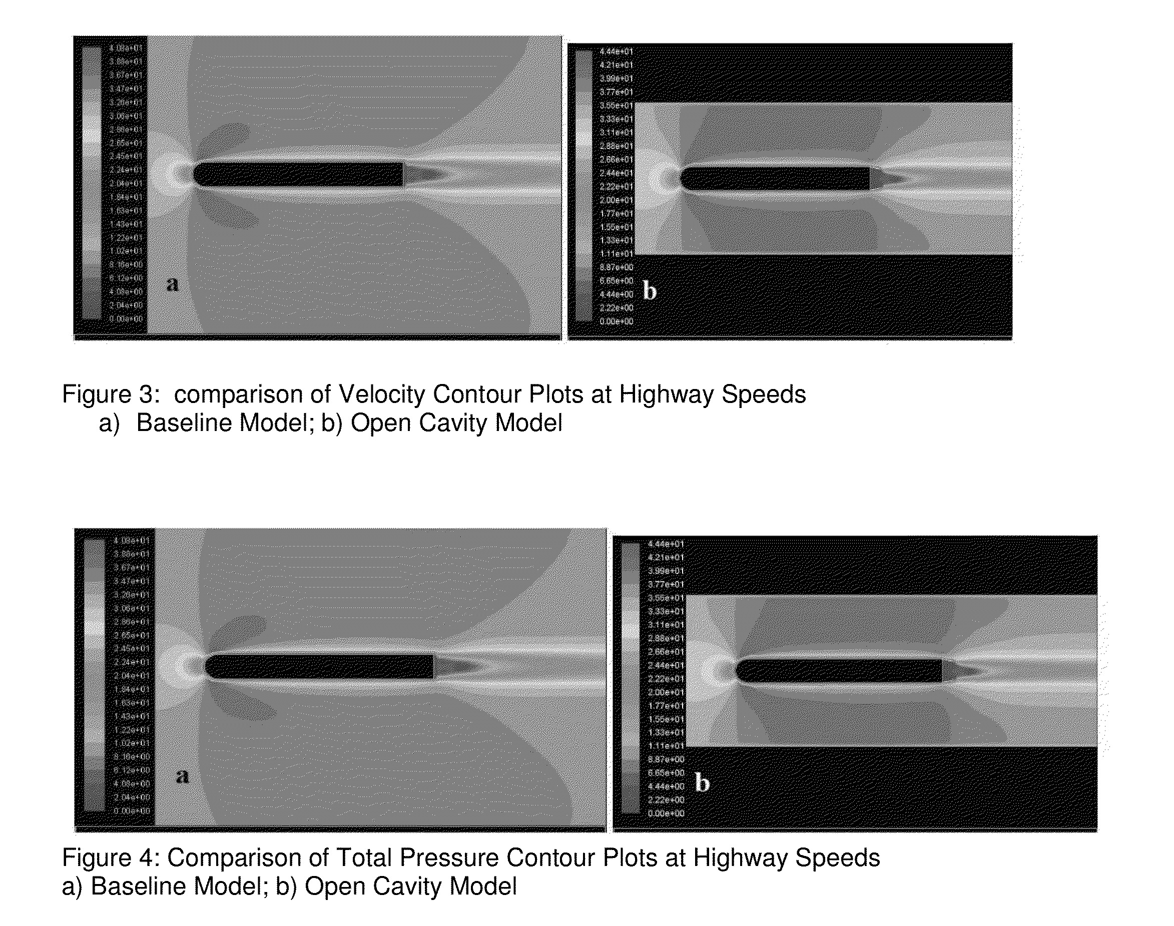
[0072]Before getting into detailed quantitative studies on arc vanes, the CFD study began with very general qualitative studies. The first of these studies was the two dimensional modeling of a simple bluff body, the length and width of a tractor trailer both with and without a drag reducing device. The bluff body was modeled f...

example 2

Experimental Apparatus

[0082]This Example describes the experimental apparatus used in the following Examples. All wind tunnel testing was conducted in the Clarkson University high speed Eiffel type wind tunnel on a 1:15.25 scale tractor trailer model. The biaxial force balance set-up was taken directly from J. D. Coon's thesis work (see “SAE Wind Tunnel Test Procedure for Trucks and Buses.” SAE International. 1981), as very little is changed from his original set-up.

[0083]During testing, the maximum velocity achieved by the wind tunnel was approximately 37 m / s, or 82.8 mph. Based on trailer width, the Reynolds number produced by this velocity is about 3.9×10⁵. If it is assumed that a full scale tractor trailer experiences an average wind speed of 70 mph, or 31.3 m / s, and that the usual width of a tractor trailer is 2.46 meters, the resulting full scale Reynolds number is approximately 5×10⁶. The SAE Wind Tunnel Test Procedure for Trucks and Buses' suggests a minimum experimental Rey...

example 3

Wind Tunnel Models

Initial Testing

[0124]This Example describes certain “initial testing” of the “wind tunnel models.” The purpose of the initial testing was to simply get an idea for how Kato's un-optimized scaled geometry worked on the tractor trailer model. Because it was a preliminary testing step, only two studies were carried out: a yaw angle study on Kato's design, and a study that examined the change in drag reduction that different configurations cause. A description of testing that occurred during this phase is set forth herein.

[0125]Using the Kato et al investigation as a starting point, the initial, exploratory design was modeled using optimal dimensions from the paper. A schematic illustrated in FIG. 15 shows Kato's experimental set-up (see also Frey, K. (1933), “Verminderung des Stroemungswiderstandes von Koepern durch Leitflaechen,”Forschung Ing. Wesen, March / April, pp. 67-74). The optimum configuration of vanes is given as ratios of the vane arc-radius to body width, v...


PUM


Abstract

The present invention relates to a vehicle having an apparatus mounted thereon for reducing aerodynamic drag and, more particularly, to a guide vane apparatus with an airfoil cross-section mounted to the aft portion of a tractor trailer.

Description

RELATED APPLICATION DATA[0001]The present application claims the benefit of U.S. provisional patent application No. 61 / 759,701, filed Feb. 1, 2013, and is hereby incorporated by reference in its entirety.BACKGROUND OF THE INVENTION[0002]1. Field of the Invention[0003]The present invention relates to a vehicle having an apparatus mounted thereon for reducing aerodynamic drag and, more particularly, to a guide vane apparatus with an airfoil cross-section mounted to the aft portion of a tractor trailer.[0004]2. Description of the Related Art[0005]Reducing the fuel consumption of passenger vehicles is an urgent world issue that is currently being addressed by scientists and engineers. In addition to passenger cars on American roadways, the US Department of Transportation (2006) reported that there were 2,010,335 combination tractor trailers registered in service in 2005. The average number of miles each vehicle traveled per year was approximately 72,325 miles and over 24.7 billion gallo...

Claims


Application Information

Patent Timeline
Patent Type & Authority Patents(United States)
IPC IPC(8): B62D35/00
CPCB62D35/001
Inventor VISSER, KENNETH D.
Owner CLARKSON UNIVERSITY
Why Eureka
Try Eureka