System for subsea cable installation

a technology for subsea cables and installation systems, which is applied in the direction of pipe laying and repair, pipe/joints/fittings, soil-shifting machines/dredgers, etc. it can solve the problems of high load, difficult to deploy cable from the vessel, and act on the cable hanging from the deck, so as to reduce the mechanical strain of the cable and avoid the risk of tangled cable

Inactive Publication Date: 2015-09-22
OCTIO
View PDF13 Cites 3 Cited by
  • Summary
  • Abstract
  • Description
  • Claims
  • Application Information

AI Technical Summary

Benefits of technology

[0008]The object of the present invention is to provide an improved system for laying / trenching cable at the sea floor in deep water for various purposes, in particular seismic cables comprising seismic sensor modules, where said system enables for controlled deployment and trenching, with minimised mechanical strain on the cable and where the risk of tangled cable is substantially avoided.
[0011]The coiling arrangement enables easy coiling of all types of cables, including seismic cables possibly also comprising sensor modules which may be asymmetrically arranged and which normally are difficult to coil since the modules get stuck in between cable sections leading to tangling.
[0012]Thanks to the invention where the cable is allocated inside the container in an predetermined ordered arrangement there is achieved a way of performing a problem free unloading of a cable from the container to the trenching vehicle where entangling of the cable is avoided, and where the cable may be pulled out from the container without any high tensions in the cable leading to minimised risk of damages. Also, since the entire cable to be installed is accommodated inside the container until trenching is commenced, the damage risk due to that mechanical strain is eliminated.
[0013]When using the cable laying system according to the present invention the weight of the trenching vehicle, including the container and the cable, will be quite significant, even as much as 10-20 tons. In some areas the seabed is very soft, and will not support the load of the vehicle. For that reason, and also for reducing the load on the umbilical cable during deployment of the vehicle, buoyancy is needed on the trenching vehicle. Known solutions include for instance attach buoyancy elements made from syntactic foam to the vehicle. However, this gives a fixed buoyancy, and it is not possible to adjust the buoyancy for changing seabed conditions or the fact that the load decrease as the cable is laid out on the seabed, and the buoyancy should therefore be reduced to maintain a constant load on the seabed. This problem is solved in that the trenching vehicle according to the invention may be equipped with buoyancy members, preferably in the form of ballast tanks filled with compressed air.
[0017]According to another aspect of the invention the buoyancy members may be divided into several compartments, with individual air flow control. This can be used to control the stability of the vehicle, and uneven offloading of cable can be compensated by the ballast / buoyancy system.
[0018]According to one aspect of the invention said elongate flexible element is a seismic cable, possibly comprising at least one sensor module integral with the element, preferably at least two sensor modules being spaced from each other and interconnected via said cable. The coiling arrangement will provide specific advantages for seismic cables, since these types of flexible elements are quite sensitive to e.g. mechanical strains and since sensor modules often leads to entanglement upon deployment. By being able to arrange the cable in a predetermined coiled configuration such problems are avoided and a comparably easy trenching is possible.

Problems solved by technology

For cables in general, and seismic cables in particular, it is very challenging to deploy cable from the vessel all the way to the ocean floor without exposing it to too much mechanical strain which could damage the structure and components.
This is especially a problem at deep waters where the distance from the surface to the seabed may be several thousand meters which of course leads to very high loads (e.g. from water currents, turbulence and / or vessel heave) acting on the cable hanging from the deck.
However such a solution brings a risk that the cable will get tangled during unwinding, and / or that the seismic stations get trapped in between layers of cable and get damaged.
However, also these two concepts will only reduce the problem, not eliminate it.

Method used


Image

  • System for subsea cable installation
  • System for subsea cable installation
  • System for subsea cable installation

Examples


Embodiment Construction

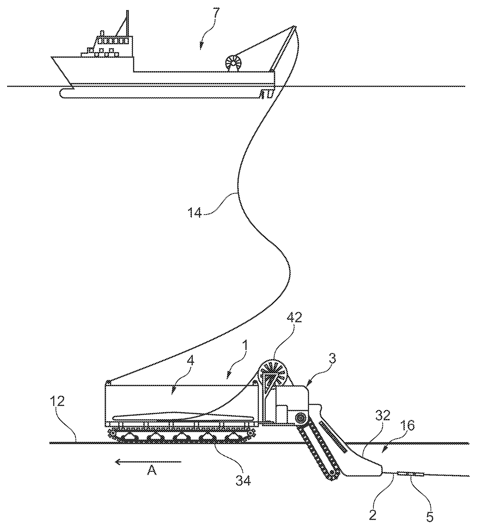
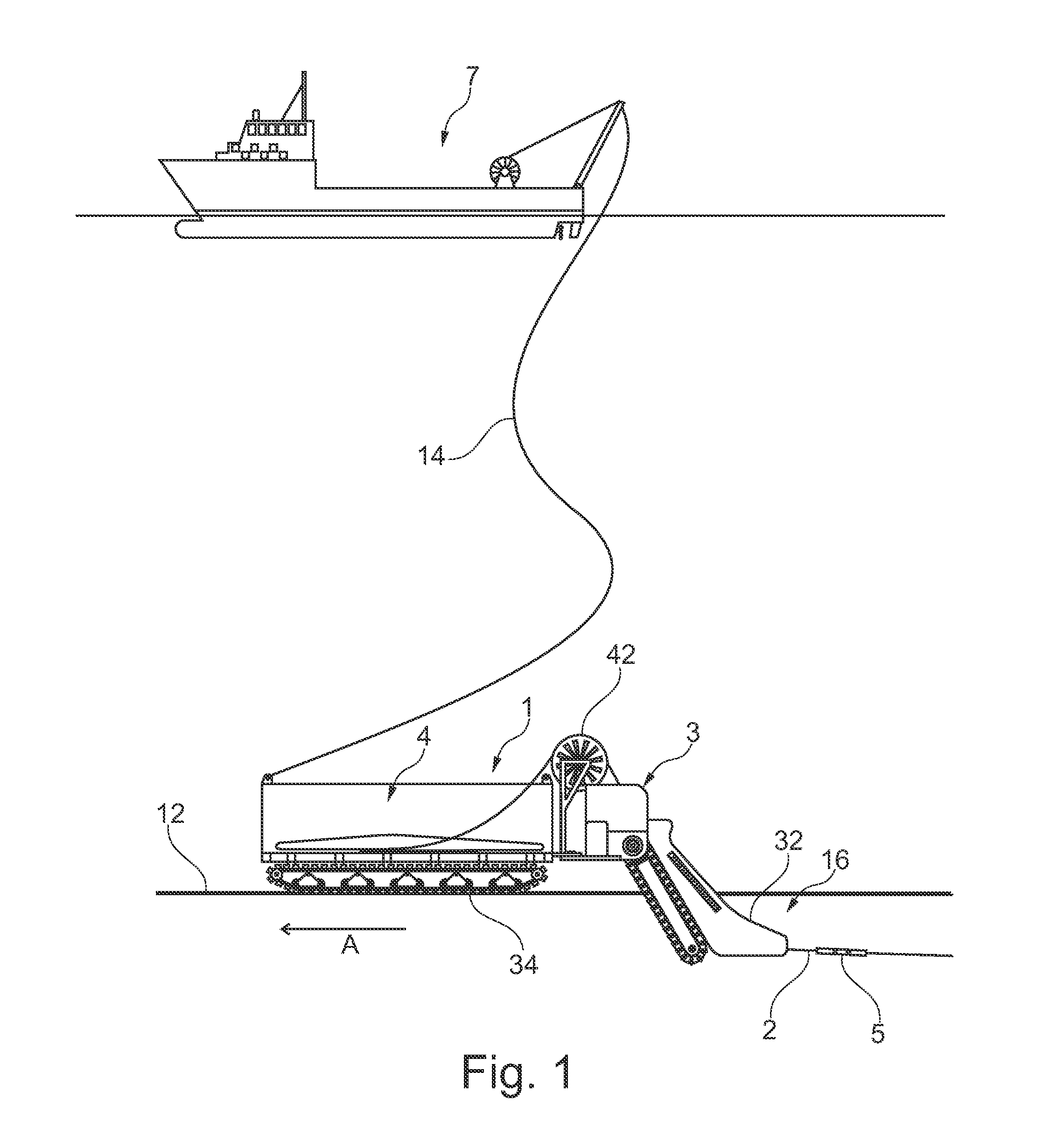
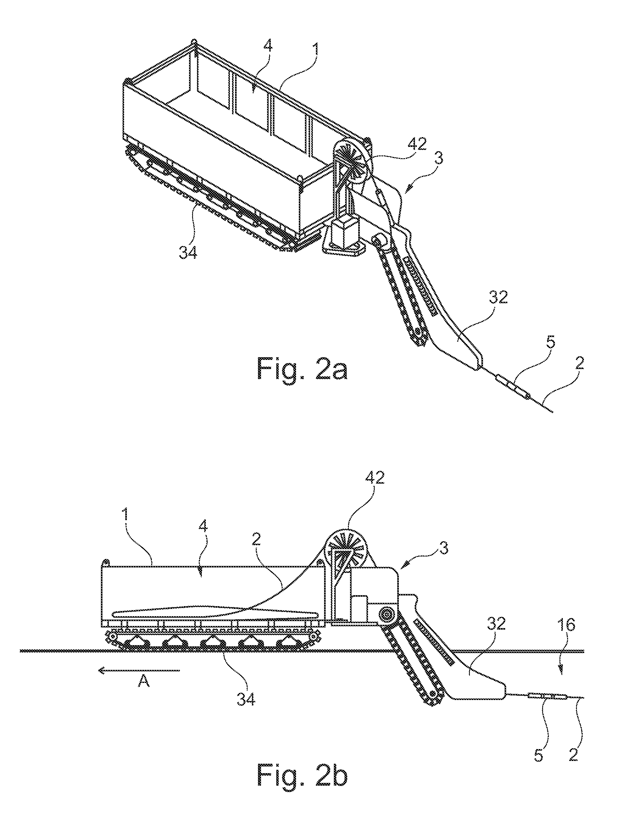
[0038]Referring first to FIG. 1 there is seen a non-limiting schematic side view of a system for subsea installation of elongate flexible element 2 according to a preferred aspect of the invention, wherein a surface vessel 7 is linked to a submersed trenching vehicle 3 via an umbilical cable 14. The umbilical cable 14 supply electric power to the vehicle 3, and provides a telemetry link for control and monitoring of vehicle and its functions so that the trenching vehicle 3 is remotely operable subsea from said surface vessel 7. Further, the trenching vehicle 3 is provided with a container 1 allocating an elongate flexible element 2 intended to be installed into the seabed 12. The elongate flexible subsea element may be a seabed pipe or a cable, such as a seismic cable, for example, having sensor modules 5 distributed rather densely along the cable. Hereinafter said elongate flexible element 2 will be referred to as “cable”. Said sensor modules form an example of an accessory 5 that ...


PUM


Abstract

The present invention relates to a system for subsea installation of elongate flexible element, comprising a container for allocating / storing / accommodating an elongate flexible element intended to be installed, said container being positioned on a trenching vehicle arranged to trench said elongate flexible element into the seabed, which container comprises a guide system arranged to control the release of the flexible element, and which trenching vehicle is further linked to a surface vessel via an umbilical cable whereby said vehicle is remotely operable subsea from said surface vessel wherein said guide system comprises a coiling arrangement for keeping the elongate flexible element in a defined coiled configuration inside said container.

Description

TECHNICAL FIELD[0001]The present invention relates to a system for subsea cable installation, comprising a container for allocating / storing / accommodating a cable intended to be installed, said container being connected to a trenching vehicle for trenching said cable into the seabed, which container comprises a guide system arranged to control the release of the cable and which container is further linked to a surface vessel via an umbilical cable wherein said container is remotely operable subsea from said surface vessel.BACKGROUND ART[0002]Underwater deployment and trenching of cable are nowadays common procedures practiced by many operators for instance when permanently installing optic, power and / or seismic cables offshore. Typically a cable is continuously deployed and submerged into the water column from a surface vessel such as a barge, a DP vessel or any other ship, pontoon or platform. A remotely operated underwater vehicle (ROV) at the ocean bottom is maneuvered from the ve...

Claims


Application Information

Patent Timeline
Patent Type & Authority Patents(United States)
IPC IPC(8): F16L1/12F16L1/16E02F9/20H02G1/10E02F5/10
CPCF16L1/165E02F5/105E02F5/106E02F5/109E02F9/2016H02G1/10
Inventor OLDERVOLL, MAGNE
Owner OCTIO
Why Eureka
Try Eureka