Heat storage apparatus for vehicle

a technology for storage apparatus and heat, applied in the direction of indirect heat exchangers, lighting and heating apparatus, machines/engines, etc., can solve the problem that the patent document 1 does not describe in detail

Inactive Publication Date: 2015-09-22
TOYOTA JIDOSHA KK
View PDF34 Cites 9 Cited by
  • Summary
  • Abstract
  • Description
  • Claims
  • Application Information

AI Technical Summary

Benefits of technology

[0019]As described above, however, even after it is determined that the required outgoing heat amount cannot be satisfied only by the heat storage amount in the heat storage material in the sensible heat storage state, the control section still performs heat release from the heat storage material in the sensible heat storage state until after the lapse of the predetermined period of time. In addition, if it is determined that the required outgoing heat amount cannot be satisfied even after the lapse of the predetermined period of time, the control section performs heat release from the heat storage material in the latent heat storage state. Accordingly, under such circumstances where the required outgoing heat amount is decreased immediately after it is determined that the required outgoing heat amount cannot be satisfied, it is possible prevent the heat storage material in the latent heat storage state from releasing heat and unnecessarily shifting to the sensible heat storage state.

Problems solved by technology

However, Patent Document 1 does not describe in detail the manner of heat release from the heat storage body.

Method used


Image

  • Heat storage apparatus for vehicle
  • Heat storage apparatus for vehicle
  • Heat storage apparatus for vehicle

Examples


first embodiment

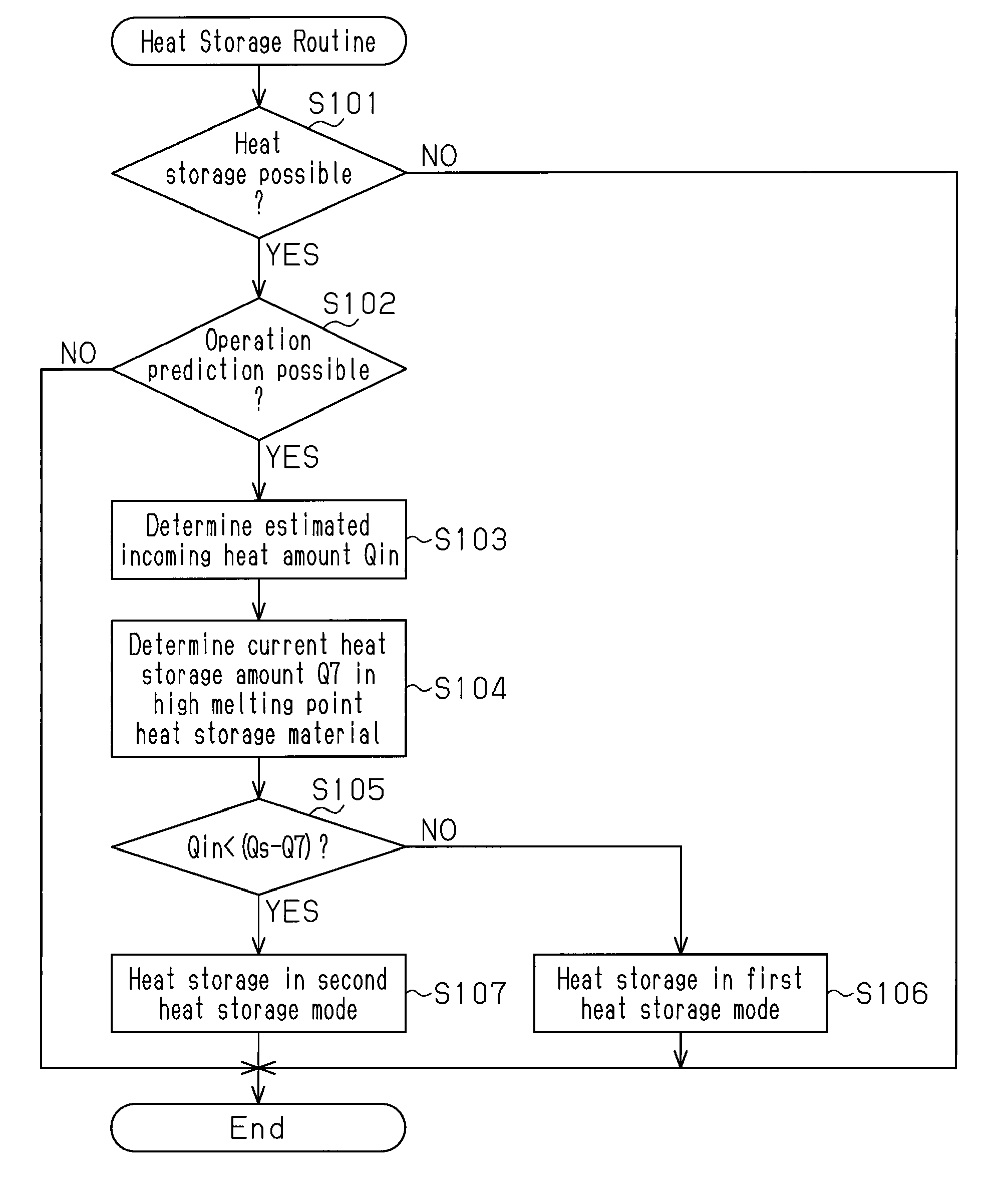
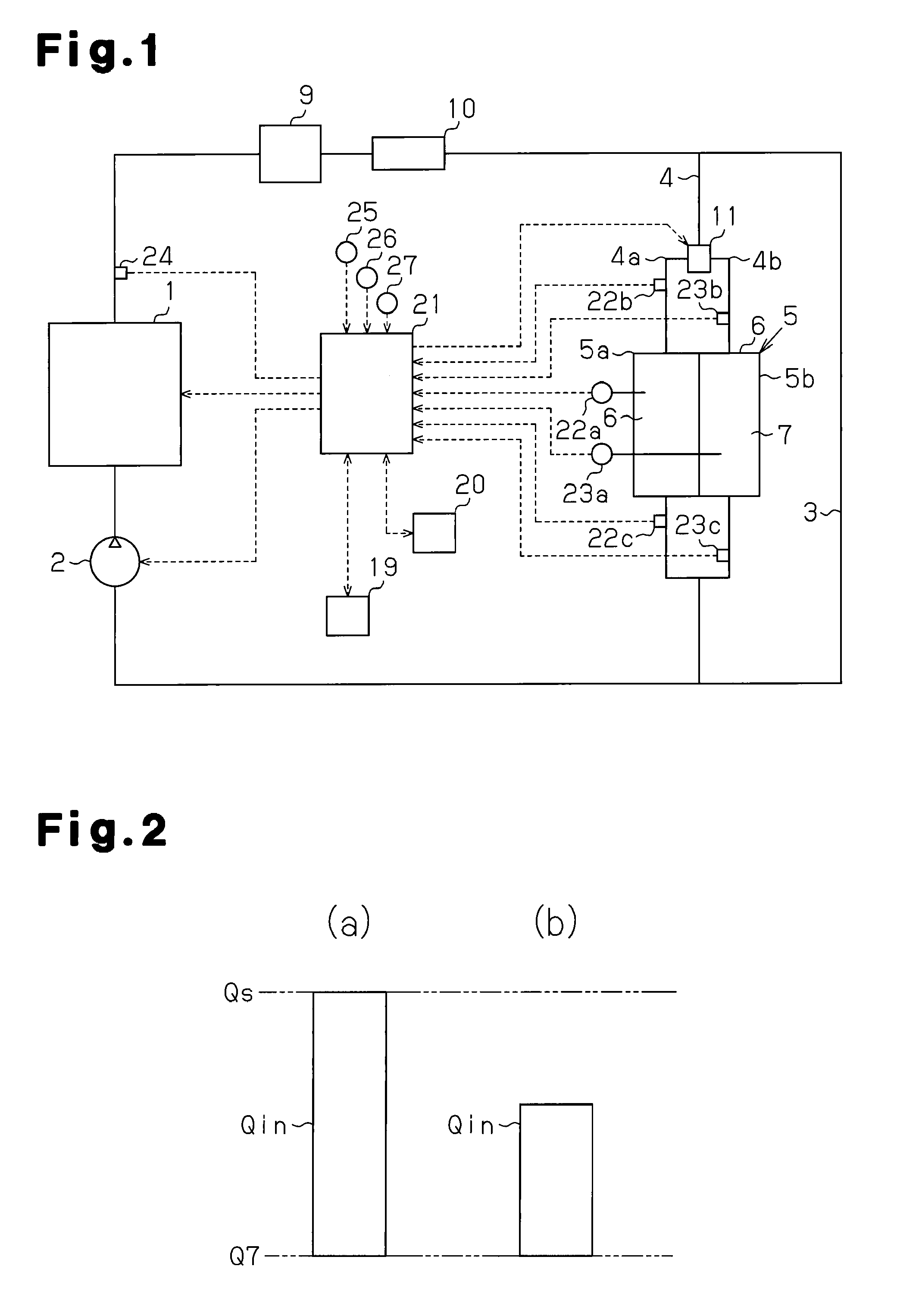
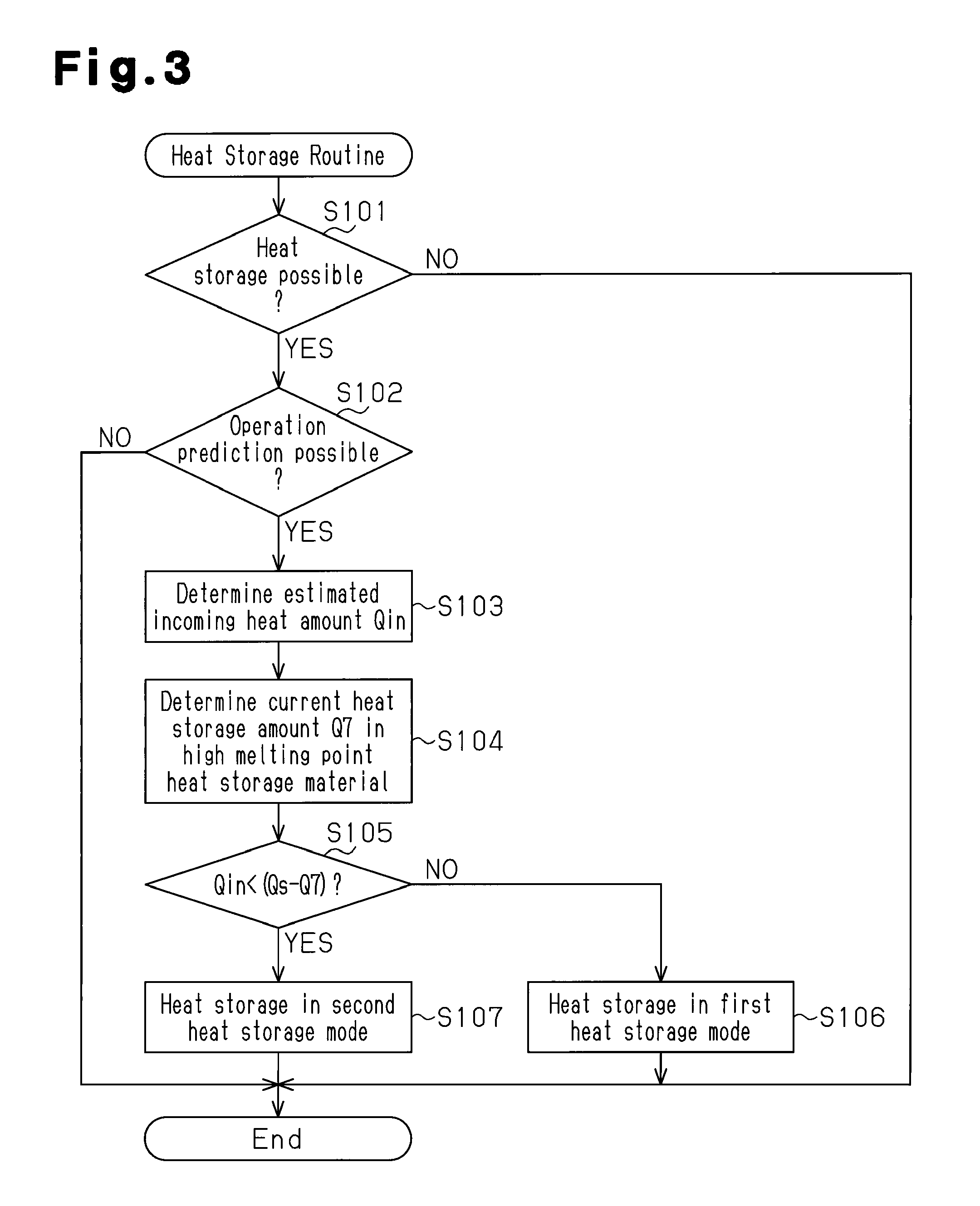
[0026]A heat storage apparatus for an automobile according to a first embodiment of the present invention will be described below with reference to FIGS. 1 to 4.

[0027]The automobile is provided with a circulation circuit for circulating coolant water (heat medium) for heat exchange with an engine 1, as shown in FIG. 1. The coolant water in the circulation circuit is circulated using an electrically-operated water pump 2, for example. In the circulation circuit, the coolant water discharged from the water pump 2 passes through the engine 1, a heater core 9, an exhaust heat recovery unit 10, and a main passage 3, and then returns to the water pump 2. The heater core 9 is intended to heat the interior of the automobile through an air-conditioner mounted in the automobile by warming air supplied from the air-conditioner by heat from coolant water. The exhaust heat recovery unit 10 is intended to recover the heat from exhaust air from the engine 1 by coolant water passing through the exh...

second embodiment

[0075]Next, a second embodiment of the present invention will be described with reference to FIG. 5.

[0076]FIG. 5 is a flowchart for a heat release routine in this embodiment. In the routine, steps (S301 to S303, S306, and S307) equivalent to steps S201 to S206 in the heat release routine in the first embodiment (FIG. 4) are performed and additional steps S304 and S305 are also performed. The additional steps (S304 and S305) are intended to determine the required outgoing amount Qout considering also heat release from the heat sources of the automobile to the coolant water in the circulation circuit.

[0077]The coolant water in the circulation circuit receives heat released from the heat sources of the automobile such as the engine 1 and the exhaust heat recovery unit 10, and increases in temperature also due to the heat release. Accordingly, the required outgoing heat amount Qout for heating the coolant water in the circulation circuit (temperature adjustment section of the automobile...


PUM

PropertyMeasurementUnit
melting pointsaaaaaaaaaa
heat releaseaaaaaaaaaa
temperatureaaaaaaaaaa

Abstract

When performing heat storage in a heat storage container accommodating a plurality of kinds of heat storage materials with different melting points, heat storage in the heat storage materials is performed such that a higher melting point heat storage material is in a latent heat storage state as much as possible. In other words, heat storage in the heat storage materials is performed in such a manner that the heat storage materials are in the latent heat storage state in which heat can be stored most effectively. In addition, when performing heat release from the heat storage container to heat coolant water in a circulation circuit, heat release is performed from the heat storage material in the sensible heat storage state as a priority, out of the heat storage materials. Accordingly, heat release from the heat storage container in the heat storage state is performed in such a manner that the heat storage materials are maintained in latent heat storage state for as a long period of time as possible. When heat release from the heat storage container is performed in this manner, the heat storage materials can be kept in the latent heat storage state for as a long period of time as possible. As in the foregoing, the heat storage container can be kept in the heat storage state for a long period of time.

Description

[0001]This is a 371 national phase application of PCT / JP2011 / 056791 filed 22 Mar. 2011, the contents of which are incorporated herein by reference.FIELD OF THE INVENTION[0002]The present invention relates to a heat storage apparatus for a vehicle.BACKGROUND OF THE INVENTION[0003]Vehicles such as automobiles are provided with a heat storage apparatus that temporarily stores surplus heat from heat sources of the vehicles in a heat storage body, and releases and uses the heat stored in the heat storage body for heating temperature adjustment sections of the vehicles and the like. In such a heat storage apparatus, employing a heat storage body capable of latent heat storage as the foregoing heat storage body is effective in increasing the amount of heat storage in the heat storage body while keeping the capacity of the heat storage body low. Latent heat storage refers to heat storage utilizing absorption and release of heat in / from a material forming the heat storage body with state cha...

Claims


Application Information

Patent Timeline
Patent Type & Authority Patents(United States)
IPC IPC(8): F28D20/02F02G5/02F02G5/00F01P11/20
CPCF28D20/028F02G5/00F02G5/02F28D20/02F01P11/20Y02E60/145Y02T10/166Y02E60/14Y02T10/12
Inventor GOTO, MIYUKISHIGA, SATORU
Owner TOYOTA JIDOSHA KK
Why Eureka
Try Eureka