
Through coolant adaptor for use on hollow spindle machine tools

a technology of coolant adaptor and hollow spindle, which is applied in the direction of tool workpiece connection, chuck, manufacturing tools, etc., can solve the problems of not allowing automatic change of tools, and reducing the generation of coolant. the effect of reducing the generation of heat energy

Inactive Publication Date: 2015-10-06
SIEMENS AG
View PDF27 Cites 1 Cited by
  • Summary
  • Abstract
  • Description
  • Claims
  • Application Information

AI Technical Summary

Benefits of technology

This solution enhances tool longevity, improves coolant supply efficiency, and allows for automatic tool changing in hollow spindle machines, reducing manual intervention and enabling high-pressure coolant delivery.

Problems solved by technology

The coolant reduces the generation of heat energy.
While it is generally no problem to provide coolant at an external contact point of the wall of the tool to the workpiece, supply of coolant to an internal contact point of the tool to the workpiece presents a problem.
In the art this problem is approached by flexible coolant pipes.
Moreover, these flexible coolant pipes do not allow an automatic changing of tools and do not allow a high pressure supply of coolant, which is required for modern high speed hollow spindle machine tools.

Method used


Image

  • Through coolant adaptor for use on hollow spindle machine tools
  • Through coolant adaptor for use on hollow spindle machine tools
  • Through coolant adaptor for use on hollow spindle machine tools

Examples


first embodiment

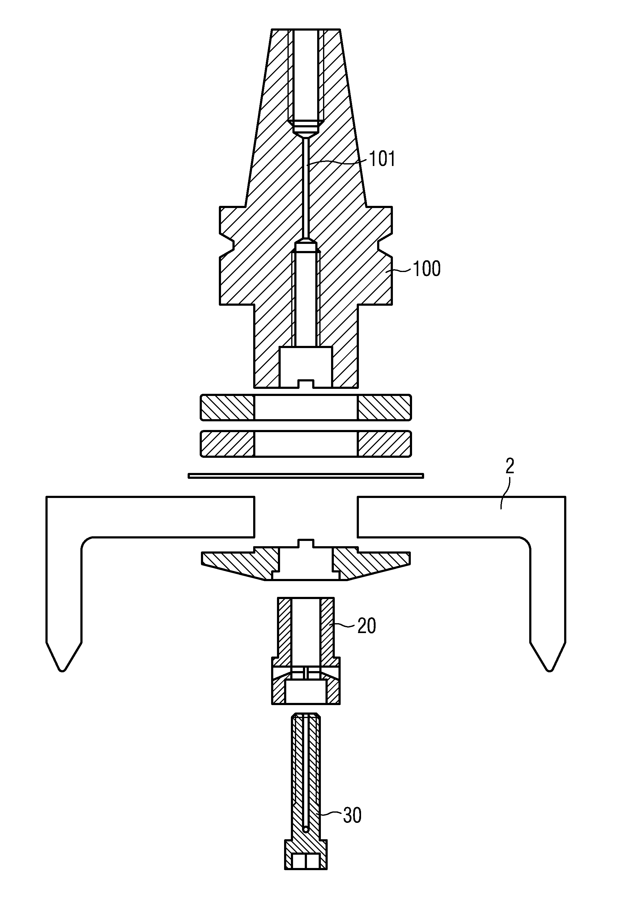
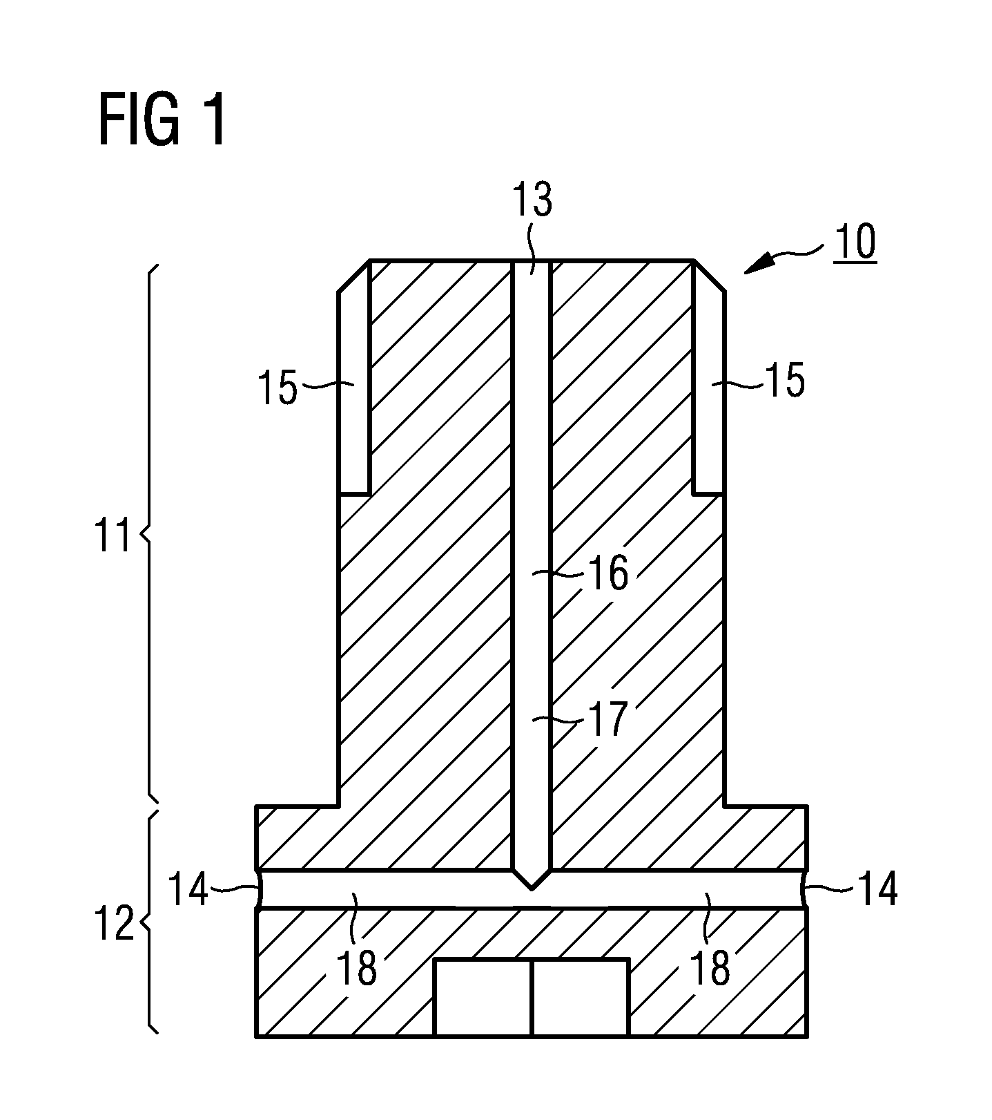
[0027]A first exemplary embodiment will be described in the following. FIG. 1 shows a cross sectional view of an adaptor 10 for fixing a tool 2 to an arbor 100 according to the present invention. Thereby, the arbor 100 can e.g. be a part of a hollow spindle machine for processing a workpiece. The tool 2 can be e.g. a grinding wheel like a cup style grinding wheel for grinding workpieces such like curvic couplings or turbines for turbine engines.

[0028]The adaptor 10 comprises an inlet opening 13 at a first part of the adaptor 10. The inlet opening 13 is connectable to a central passage way 101 of the arbor 100. Moreover, the adaptor comprises at least one outlet opening 14 at a second part 12 of the adaptor 10. The inlet opening 13 is connected to the at least one outlet opening 13 by a fluid distribution passage way 16.

[0029]In FIG. 1 an adaptor 10 with two outlet openings 14 is shown. The outlet openings 14 are disposed on the side face of the second part 12 of the adaptor 10. Howe...

second embodiment

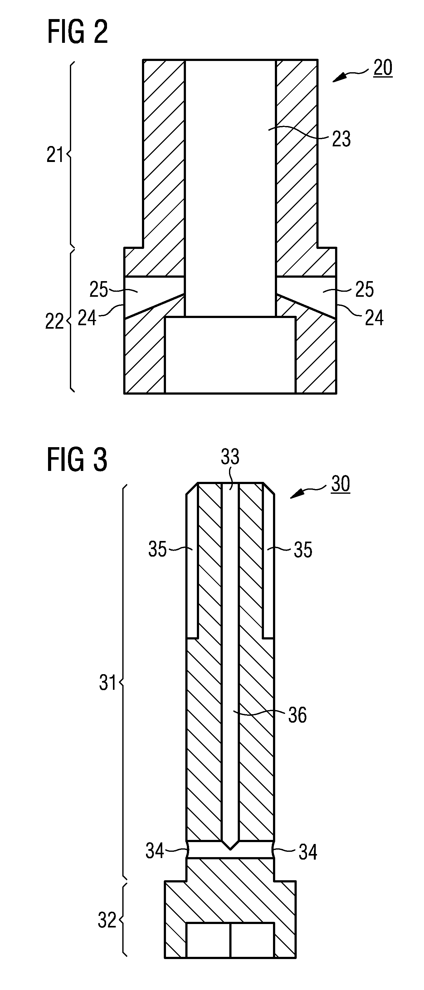
[0047]When using a cup style tool 2 the system consisting of the adaptor 20 and the connection device 30 according to the present invention provides the advantage that coolant can be delivered to internal contact points of the tool 2 to the workpiece without the need for flexible coolant pipes. Therefore, a constant manual adjustment of these flexible coolant pipes is omitted. Moreover, the above described system allows a high pressure supply of coolant required for modern high speed hollow spindle machine tools, which is not possible with flexible coolant pipes known in the art. A further advantage of the above described system is that automatic changing of tools 2 is possible in the case a hollow spindle machine with an automated tool changing system is used.

[0048]A further advantage of the system consisting of the adaptor 20 and the connection device 30 is facilitated positioning of the adaptor 20 in relation to the arbor 100.

[0049]FIG. 4 shows an assembly example of a hollow spi...


PUM


Abstract

An adaptor and a connection device are provided. The adaptor and the connection device fix a tool to an arbor of a hollow spindle machine. The adaptor has an inlet opening at a first part of the adaptor, the inlet opening being connectable to the central passage way of the arbor. The adaptor has an outlet opening at a second part of the adaptor, the second part radially protruding over the first part and being adapted for holding the tool. The adaptor has a connection device for fixing the adaptor to the arbor and a fluid distribution passage way connecting the inlet opening with the outlet opening so that the coolant is supplied to the tool via the outlet opening of the adaptor.

Description

CROSS REFERENCE TO RELATED APPLICATIONS[0001]This application is the US National Stage of International Application No. PCT / EP2011 / 058901 filed May 31, 2011 and claims the benefit thereof. The International Application claims the benefits of European application No. 10165517.3 filed Jun. 10, 2010, both of the applications are incorporated by reference herein in their entirety.FIELD OF THE INVENTION[0002]The present invention relates to hollow spindle machines using tools. In particular the present invention relates to an adaptor being adapted for fixing a tool or a cup style tool to an arbor and being adapted for providing coolant to internal contact points of a cup style tool to a workpiece. The present invention finds application in manufacture of curvic couplings, of turbines for turbine engines, and of vanes.BACKGROUND OF THE INVENTION[0003]In the manufacture process of curvic couplings, central discs of turbines, and vanes, for instance, tools or cup style tools like cup style ...

Claims


Application Information

Patent Timeline
Patent Type & Authority Patents(United States)
IPC IPC(8): B24B55/02B23B31/02B23Q11/10
CPCB24B55/02B23B31/02B23Q11/1023B23B2231/24B23B2240/24B23B2250/12B23C2240/245B23C2250/12
Inventor BUTLER, SHANELANES, GORDON
Owner SIEMENS AG
Learn More