Vehicle headlamp

a headlamp and headlamp technology, applied in the field of headlamps, can solve the problems of not considering the means of dispersion reduction, and achieve the effects of reducing the dispersion in the relative position between the semiconductor-type light source and the light control member, improving the manufacturing efficiency, and reducing the dispersion in the light distribution pattern

Inactive Publication Date: 2015-10-06
ICHIKOH IND LTD
View PDF4 Cites 5 Cited by
  • Summary
  • Abstract
  • Description
  • Claims
  • Application Information

AI Technical Summary

Benefits of technology

[0008]The present invention has been made in order to solve the above described problem that it is important to reduce the dispersion in relative position between the semiconductor-type light source and the light control member and then reduce the dispersion in light distribution pattern.
[0022]The vehicle headlamp according to the first aspect of the present invention is provided in such a manner that a cover member is fixed to a mount member so as to be integrated with a semiconductor-type light source, and to the cover member, a light control member is mounted so as to be changeably movable between a first location and a second location. As a result, dispersion in relative position between the semiconductor-type light source and the light control member can be reduced. In this manner, dispersion in light distribution pattern can be reduced, making it possible to contribute to safe driving. In addition, a dimensional tolerance between the semiconductor-type light source and the light control member can be mitigated, its related manufacturing efficiency is improved, and its related manufacturing costs can be reduced accordingly.
[0023]The vehicle headlamp according to the second aspect of the present invention is provided in such a manner that a rotation center shaft of a rotation mechanism is positioned on an opposite side of a lens with respect to a semiconductor-type light source that is fixed to a mount member. As a result, a light control member can be switched in such a manner as to be rotationally moved between a first location with a narrow gap and a second location with a narrow gap. In this manner, dimensions in rotation movement switching direction between the first location and the second location of a lamp unit can be reduced, and the lamp unit can be reduced in size accordingly.
[0024]The vehicle headlamp according to the third aspect of the present invention is provided in such a manner that a guide protrusive portion is positioned on an opposite side of a lens with respect to a semiconductor-type light source that is fixed to a mount member. As a result, a light control member can be slidably moved and switched between a first location with a narrow gap and a second location with a narrow gap. In this manner, dimensions in slide movement switching direction between the first location and the second location of a lamp unit can be reduced, and the lamp unit can be reduced in size accordingly.

Problems solved by technology

However, in the conventional vehicle headlamp, no consideration has been taken as to means for reducing dispersion in relative position between the light source (the semiconductor-type light source) and the first reflection surface and the second reflection surface (the light control member).

Method used


Image

  • Vehicle headlamp
  • Vehicle headlamp
  • Vehicle headlamp

Examples


first embodiment

[0053](Description of Configuration in First Embodiment)

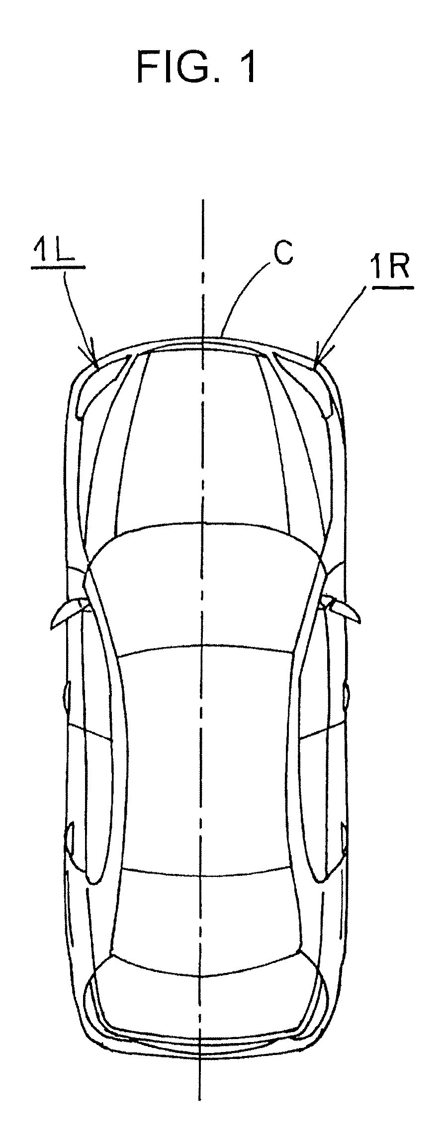
[0054]FIG. 1 to FIG. 23 each shows a first embodiment of a vehicle headlamp according to the present invention. Hereinafter, a configuration of the vehicle headlamp according to the embodiment will be described. In FIG. 1, reference codes 1L and 1R designate vehicle headlamps according to the embodiment (such as headlamps, for example). The vehicle headlamps 1L and 1R are mounted at both of the left and right end part of a front part of a vehicle C. Hereinafter, the left side vehicle headlamp 1L that is mounted on the left side of the vehicle C will be described. It is to be noted that the right side vehicle headlamp 1R that is mounted on the right side of the vehicle C forms a construction that is substantially identical to that of the left side vehicle headlamp 1L; and therefore, a duplicate description is not given.

[0055](Description of Lamp Unit)

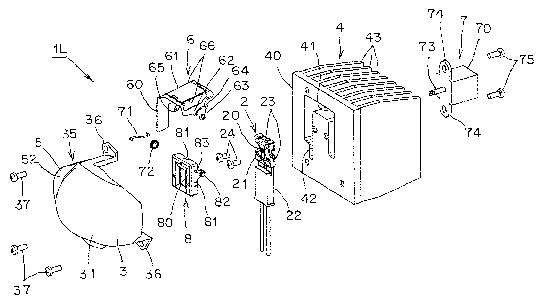
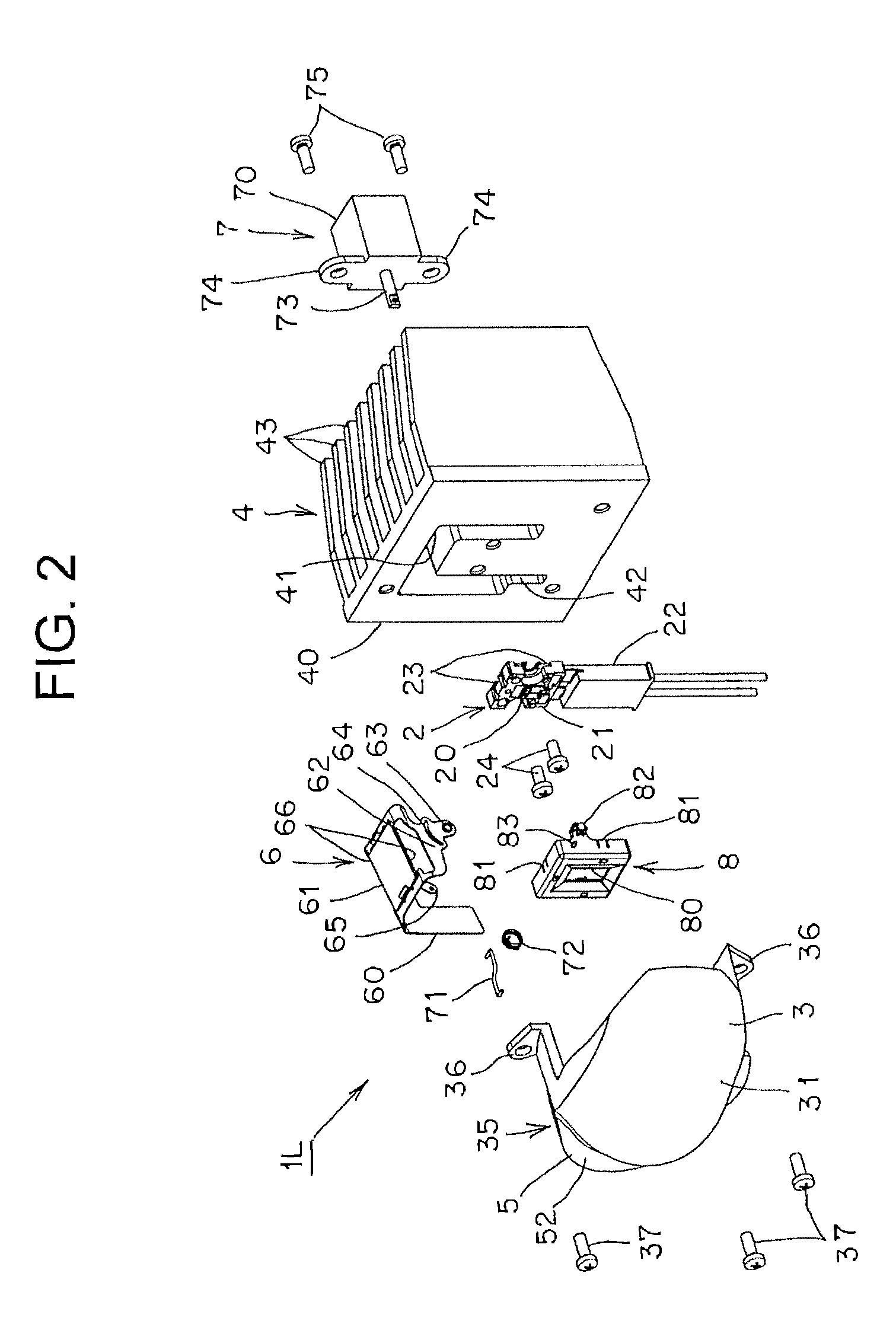
[0056]The vehicle headlamp 1L, as shown in FIG. 2 to FIG. 8, is provided with: ...

second embodiment

[0130](Description of Second Embodiment)

[0131]FIG. 24 shows a second embodiment of a vehicle headlamp according to the present invention. Hereinafter, the vehicle headlamp according to the second embodiment will be described. In the figure, like constituent elements shown in FIG. 1 to FIG. 23 are designated by like reference numerals.

[0132]A cover member 800 of the vehicle headlamp according to the second embodiment, as is the case with the cover member 8 of the vehicle headlamp according to the first embodiment described previously, has a window portion 801, a shaft 802, and a pin 803, and a mount piece 805 having a small circular through hole is integrally provided on each of the left and right sides.

[0133]The vehicle headlamp according to the second embodiment is provided in such a manner that in a state in which a semiconductor-type light source 2 is sandwiched between the cover member 800 and a heat sink member 4, the mount piece 805 of the cover member 800 is fixed to the heat...

third embodiment

[0134](Description of Third Embodiment)

[0135]FIG. 25 to FIG. 27 each show a third embodiment of a vehicle headlamp according to the present invention. Hereinafter, the vehicle headlamp according to the third embodiment will be described. In the figures, like constituent elements shown in FIG. 1 to FIG. 24 are designated by like reference numerals.

[0136]The vehicle headlamps 1L and 1R according to the first embodiment and the vehicle headlamp according to the second embodiment, as described previously, are provided in such a manner that the light control member 6 is mounted to the cover members 8 and 800 so as to be changeably rotatable and movable between the first location and the second location, and the rotation center shaft O1 of the rotation mechanism is positioned on the opposite side of the lens 35 (on the rear side) with respect to the semiconductor-type light source 2 that is fixed to the heat sink member 4.

[0137]On the other hand, the vehicle headlamp according to the thir...


PUM


Abstract

The present invention provides a semiconductor-type light source 2, a lens 35, a heat sink member 4, a light control member 6, a driving member 7, and a cover member 8. The cover member 8 is fixed to a fixing surface of the heat sink member 4 such a manner as to be integrated with the semiconductor-type light source 2. The light control member 6 is mounted to the cover member 8 in such a manner as to be changeably movable between a first location and a second location. As a result, the present invention is capable of reducing dispersion in relative position between the semiconductor-type light source 2 and the light control member 6, and reducing dispersion between a light distribution pattern for low beam LP and a light distribution pattern for high beam HP.

Description

CROSS REFERENCE TO RELATED APPLICATIONS[0001]This application claims priority of Japanese Patent Application No. 2011-286657 filed on Dec. 27, 2011. The contents of the application are incorporated herein by reference in their entirety.BACKGROUND OF THE INVENTION[0002]1. Field of the Invention[0003]The present invention relates to a vehicle headlamp that is capable of causing light from a semiconductor-type light source to be incident to a lens, illuminating the incident light from the lens forward of a vehicle, as a predetermined light distribution pattern, and switching the light distribution pattern.[0004]2. Description of the Related Art[0005]A vehicle headlamp of such type is conventionally known (for example, Japanese Unexamined Patent Application Publication No. 2011-113732). Hereinafter, the conventional vehicle headlamp will be described.[0006]A conventional vehicle headlamp is provided with: a light source; a lens; a first reflection surface configured to rotate around a r...

Claims


Application Information

Patent Timeline
Patent Type & Authority Patents(United States)
IPC IPC(8): B60Q1/04F21S8/10
CPCB60Q1/04F21S48/1154F21S48/1258F21S48/1778F21S48/321F21S41/143F21S41/255F21S41/265F21S41/683F21S41/689F21S41/692F21S41/695F21S45/47
Inventor ABE, TOSHIYA
Owner ICHIKOH IND LTD
Why Eureka
Try Eureka