Tire inflation system

Active Publication Date: 2015-10-06
APERIA TECH
View PDF131 Cites 30 Cited by
  • Summary
  • Abstract
  • Description
  • Claims
  • Application Information

AI Technical Summary

Problems solved by technology

Tires that are not optimally pressurized contribute to low fuel efficiency.
However, it is often inconvenient and inefficient for truck drivers to constantly stop, check, and inflate the vehicle tires to the optimal pressure, leading to the persistence of less-than-optimal fuel efficiency in most trucks.
This problem has led to several auto-inflating tire systems.
Conventional auto-inflating tire systems are either central or distributed, but each suffers from its own set of drawbacks.
Central inflation systems are complex and expensive, and require significant work for aftermarket installation (drilling through axles, tapping existing air lines, etc).
Distributed systems are mounted at each wheel and can be less expensive, but the potential for reduced cost is typically at the expense of the continuous replacement of the device (which fails due to the harsh wheel environment).
However, conventional passive pressurization systems suffer from several problems.
First, conventional passive pressurization systems using r

Method used


Image

  • Tire inflation system
  • Tire inflation system
  • Tire inflation system

Examples


Embodiment Construction

[0023]The following description of the preferred embodiments of the invention is not intended to limit the invention to these preferred embodiments, but rather to enable any person skilled in the art to make and use this invention.

1. Pump System

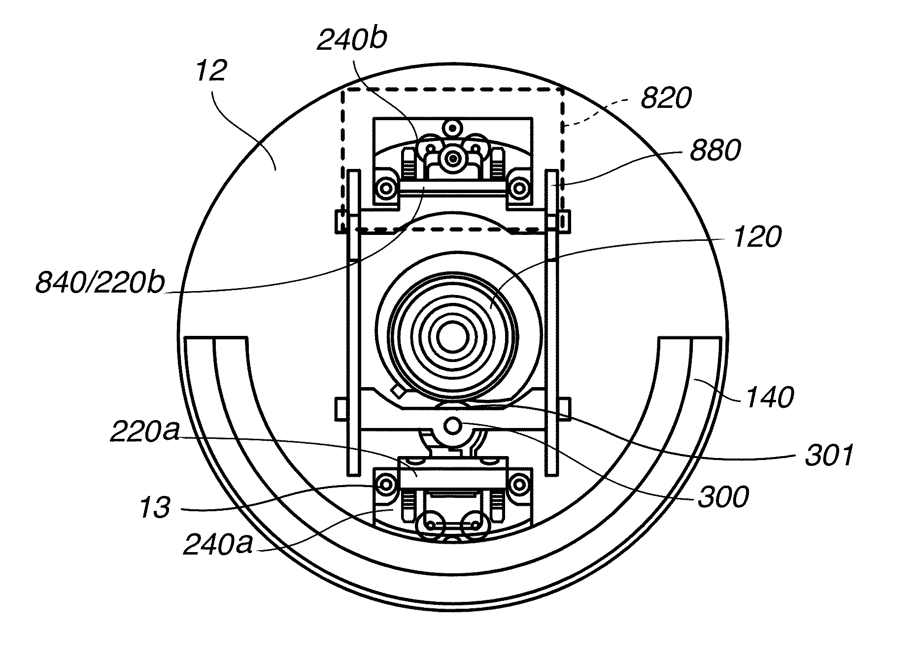
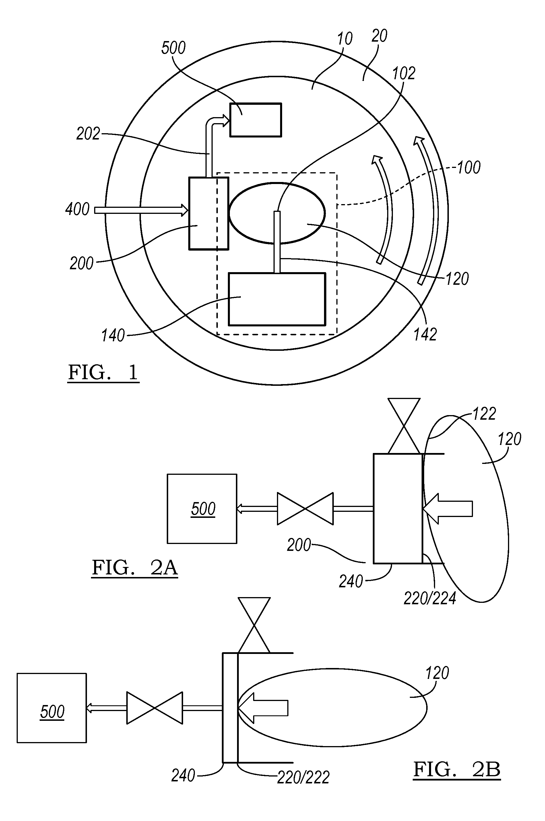
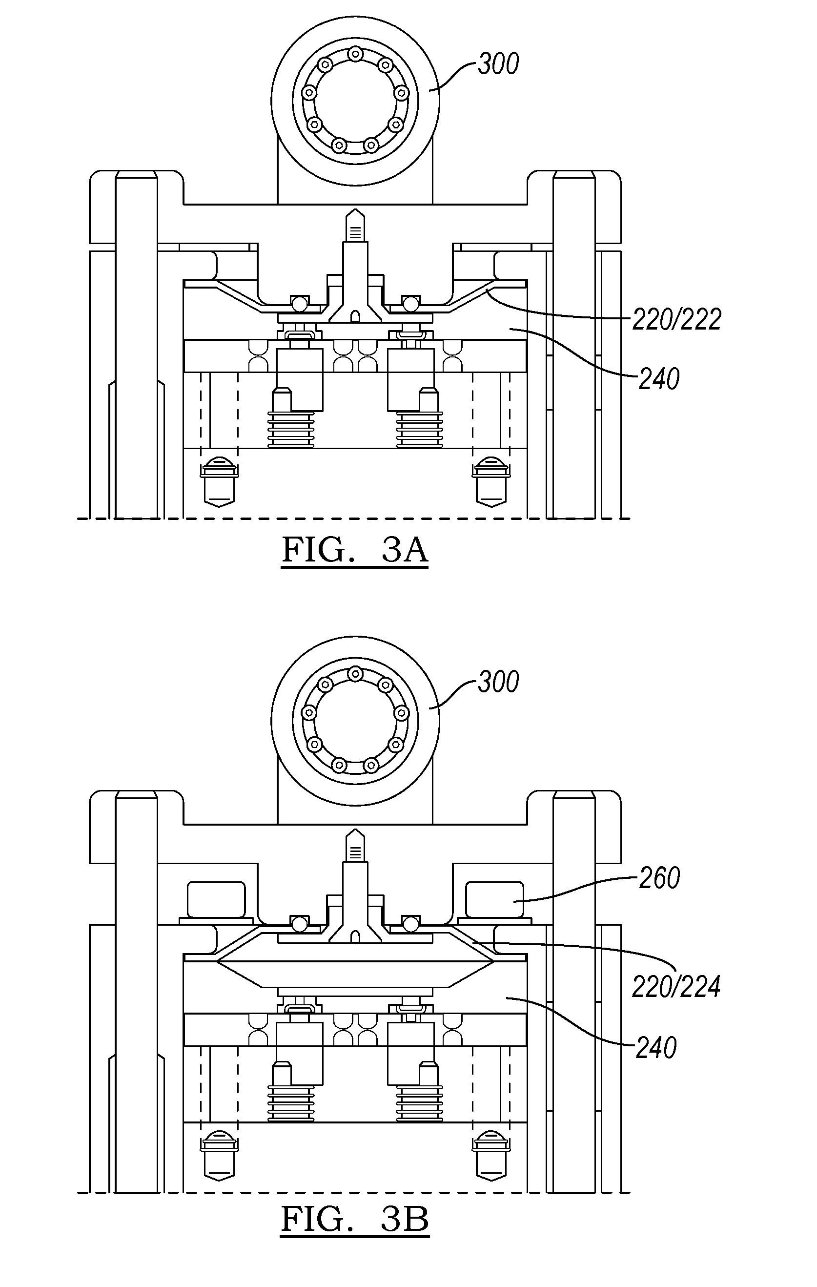
[0024]As shown in FIG. 1, the pump system 10 includes a drive mechanism 100 including a cam 120 coupled to an eccentric mass 140, a primary pump 200 including a reciprocating element 220 and a pump body 240, and a force translator 300 coupling the cam 120 to the reciprocating element 220. The pump system 10 functions to translate rotational motion into linear motion. More preferably, the pump system 10 functions to translate relative motion between the primary pump 200 and cam 120 into a pumping force, wherein the eccentric mass 140 retains the cam position relative to a gravity vector while the primary pump 200 rotates relative to the cam 120 (e.g., with a rotating surface 20). The pump system 10 preferably additionally functions to pressuri...


PUM


Abstract

A tire inflation system including a drive mechanism having a rotational axis, a pump cavity positioned a radial distance away from the axis of rotation, and a force translator coupling the rotational axis to the pump cavity. The drive mechanism includes a cam comprising an arcuate bearing surface having a non-uniform curvature, the cam rotatable about the rotational axis, and an eccentric mass couple to the cam that offsets a center of mass of the drive mechanism from the rotational axis. The pump cavity is rotatably coupled to the cam, wherein the pump cavity includes an actuating element and a chamber. The force translator couples the arcuate bearing surface to the actuating element, wherein the force translator includes an axis having an arcuate position fixed to an arcuate position of the pump cavity.

Description

CROSS-REFERENCE TO RELATED APPLICATIONS[0001]This application is a continuation of co-pending U.S. patent application Ser. No. 13 / 797,826, filed 12 Mar. 2013, which claims the benefit of U.S. Provisional Application No. 61 / 613,406 filed 20 Mar. 2012, U.S. Provisional Application No. 61 / 637,206 filed 23 Apr. 2012, and U.S. Provisional Application No. 61 / 672,223 filed 16 Jul. 2012, which are incorporated in its entirety by this reference.[0002]This application is also related to U.S. application Ser. No. 13 / 469,007 filed 10 May 2012, which is incorporated in its entirety by this reference.TECHNICAL FIELD[0003]This invention relates generally to the pumping field, and more specifically to a new and useful passive pump system in the pumping field.BACKGROUND[0004]Tires that are not optimally pressurized contribute to low fuel efficiency. These effects are particularly felt in the trucking industry, where long distances and large loads amplify the effects of an underinflated tire. However...

Claims


Application Information

Patent Timeline
IPC IPC(8): B60S5/04F04B17/00F04B49/08F16H25/08F04B9/04F04C25/00F16F15/14B60C23/12B60C23/00
CPCF04B49/08B60C23/00B60C23/001B60C23/003B60C23/12B60S5/043F04B9/04F04B9/042F04B17/00F04C25/00F16F15/1485F16H25/08Y10T74/2107Y10T74/2128Y10T137/86002B60C23/127B60C23/137F03G3/06Y10T74/2117F04B35/01F17D3/00H02K7/18
Inventor RICHARDSON, BRANDONCARLBERG, DAVIDSHELANDER, AGUSTUS
Owner APERIA TECH
Why Eureka
Try Eureka