Connecting socket for filter hoses

a technology for connecting sockets and filter hoses, which is applied in the direction of hose connections, couplings, separation processes, etc., can solve the problems of filter hoses being detached from the connecting socket when under load, and additional costs, and achieve the effect of producing inexpensively

Inactive Publication Date: 2015-10-06
MANN HUMMEL GMBH
View PDF14 Cites 1 Cited by
  • Summary
  • Abstract
  • Description
  • Claims
  • Application Information

AI Technical Summary

Benefits of technology

[0006]It is therefore an object of the present invention to provide a connecting socket for filter hoses that provides for a stable and seal-tight connection of filter hose and connecting socket and that can be produced inexpensively.
[0010]By folding over the end section of the filter hose, a great resistance is provided relative to pulling out the filter hose from the connecting socket because when pulling the filter hose out of the connecting socket the folded-over contact section must be greatly deformed. At the same time, the two layers of the filter hose with the interposed inner part provide a kind of labyrinth seal with particularly high seal-tightness. By means of the outer part, the stability of the connection between the filter hose and the connecting socket is further improved and the seal-tightness is increased. In this context, the outer sleeve pushes the folded-over end section or contact section of the filter hose against the contact surface of the inner part in such a way that a seal-tight connection between contact surface and filter hose is formed.
[0011]According to a preferred embodiment, the outer part has an inner sleeve that is connected by a transition section with the outer sleeve; the inner sleeve is arranged within the outer sleeve, is spaced radially from the outer sleeve, and extends at least partially in the area of the contact surface within the inner part. In this way, the filter hose extending within the inner part can be pressed radially against the inner part; this causes an additional sealing action of the filter hose relative to the inner part because an additional contact surface that is subjected to contact pressure is provided. Moreover, the tensile load of the connection of the filter hose and connecting socket is increased because the folded-over section is stabilized in that the filter hose is pressed against the inner part on both sides in radial direction.
[0013]Preferably, the contact surface is at least partially designed as a knurled surface. In this way, the force transmission counteracting sliding of the filter hose off the contact surface is improved. Moreover, for example, an undulated rippled knurled surface can increase the seal-tightness between filter hose and contact surface.
[0014]The contact surface can at least partially be designed as a sawtooth profile whose first, more flat tooth flanks are oriented in the direction toward the first end and whose second steeper flanks are facing away from the first end. The sawtooth profile forms thus a kind of barbed hook surface that avoids sliding of the pushed-on filter hose off the contact surface. At the same time, the flat flanks ensure easy pushing of the filter hose onto the sawtooth profile contact surface. Conceivable is also an embodiment of the contact surface as an undulated profile.
[0017]Preferably, the transition section with which the inner sleeve of the outer part is connected with the outer sleeve is elastically designed. In this way, the inner sleeve and the outer sleeve can elastically spread apart with spring-back function so that their spacing is enlarged. This enables an elastic clamping action acting on the filter hose. Filter hoses with different material thickness can thus be securely held on one and the same connecting socket.

Problems solved by technology

The connecting sockets of the prior art have the disadvantage that seals for sealing the filter hose on the connecting socket are provided between connecting socket and filter hose; this leads to additional costs.
Moreover, the action of simply pushing the filter hose onto the connecting socket provides for an insufficient stability of the connection of filter hose and connecting socket with the risk that the filter hose can become detached from the connecting socket when under load.

Method used


Image

  • Connecting socket for filter hoses
  • Connecting socket for filter hoses
  • Connecting socket for filter hoses

Examples


Embodiment Construction

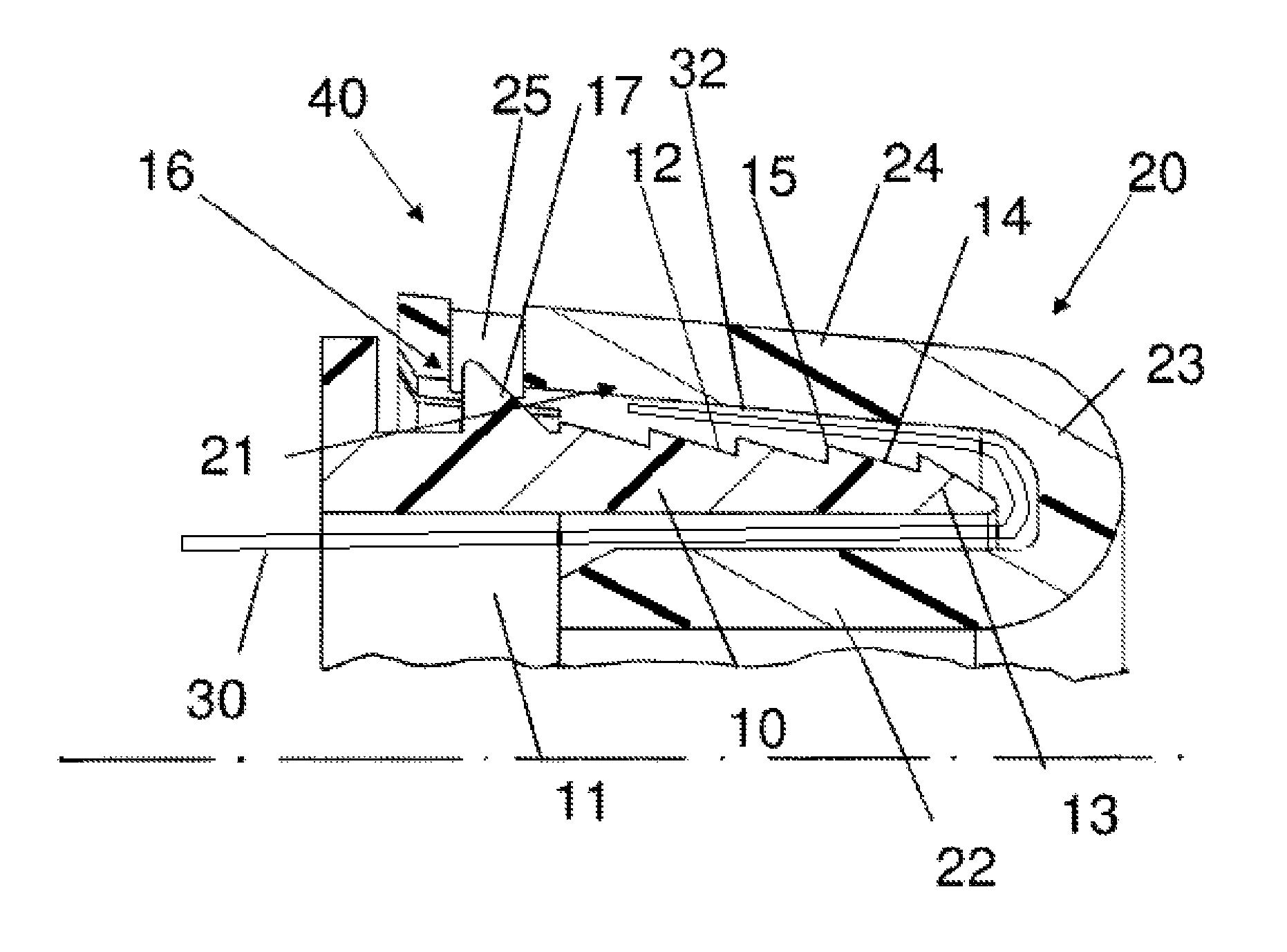
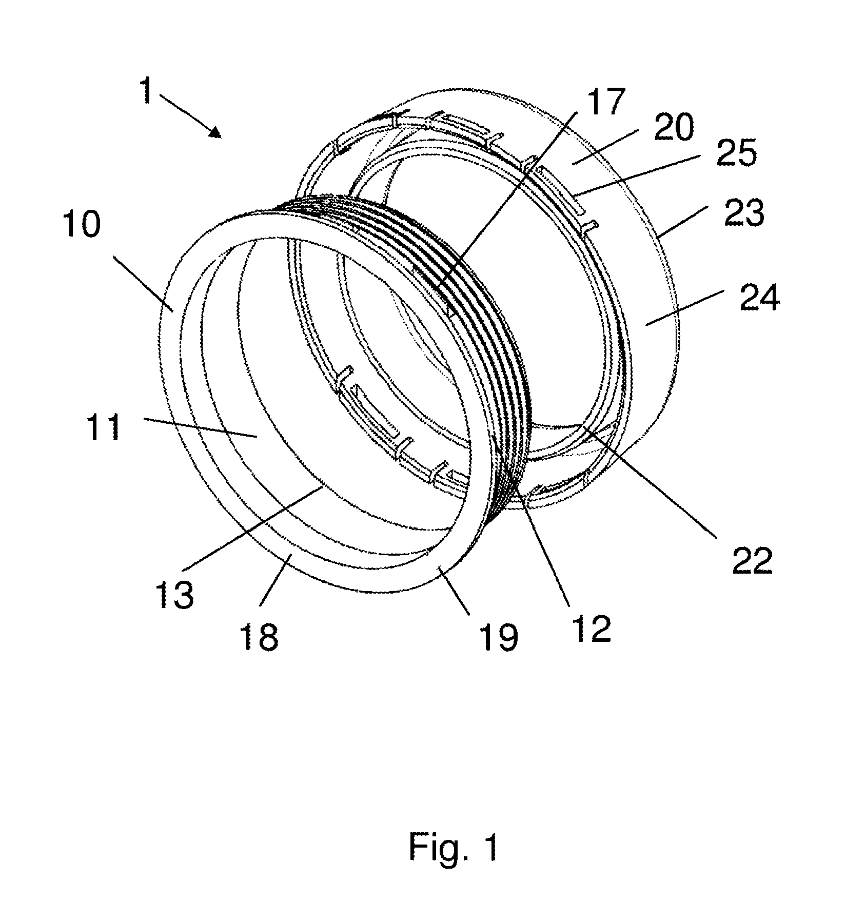
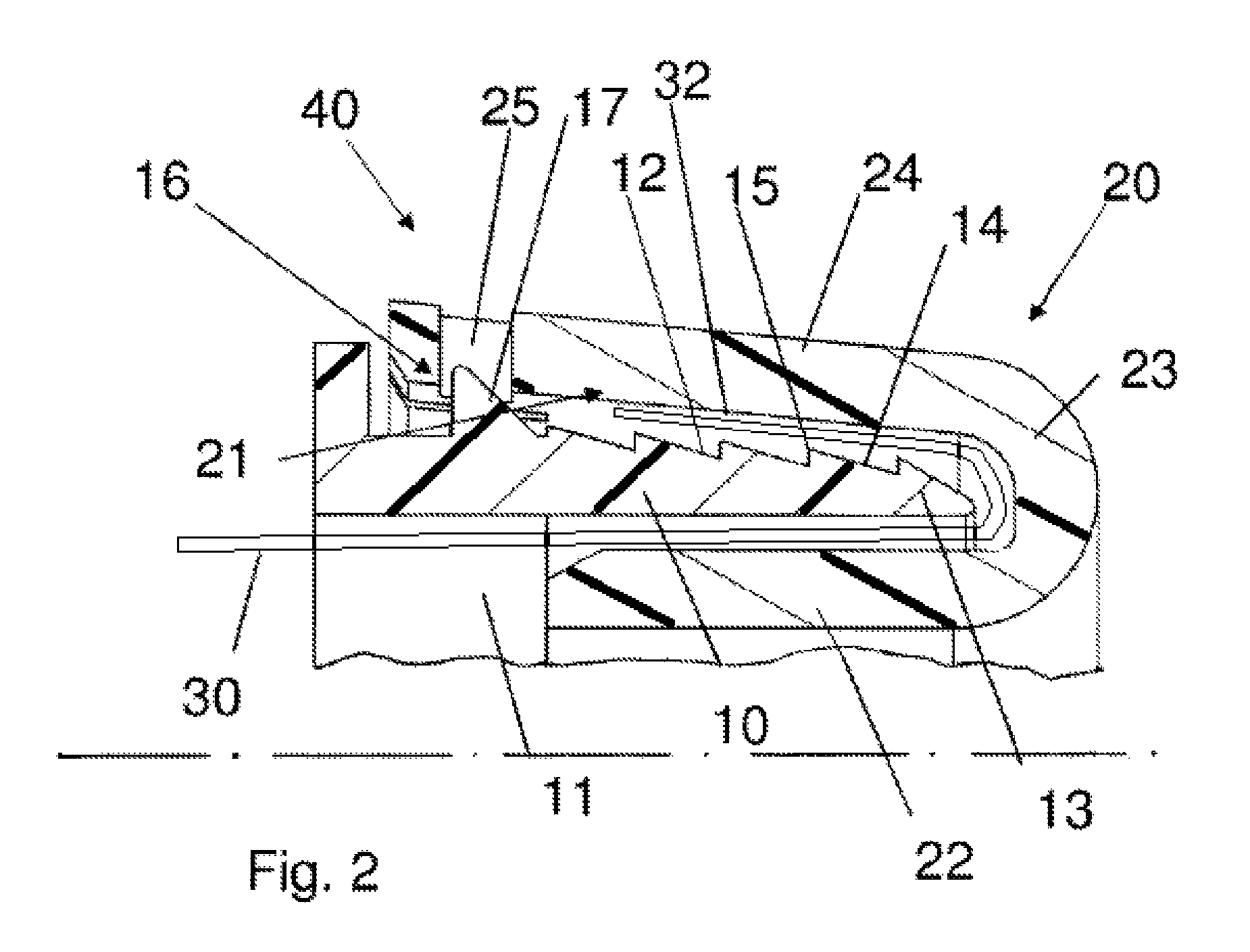
[0033]FIG. 1 shows a schematic perspective illustration of a connecting socket 1 according to a first embodiment. The connecting socket 1 comprises an inner part 10, illustrated to the left in the drawing, and an outer part 20, illustrated to the right in the drawing. The outer part 20 has an outer sleeve 24 that has a transition section 23 which is passed into an inner sleeve 22. When the inner part 10 is axially inserted into the outer part 20, the inner part 10 extends partially with its first end 13 between the outer sleeve 24 and the inner sleeve 22.

[0034]The inner part 10 has a through opening 11 that is provided in order to receive a filter hose 30 (filter hose 30 is only illustrated in FIG. 2). The filter hose 30 is pushed through the through opening 11 and its end section is then folded over about the first end 13 of the inner part 10. The folded-over end section 32 of the filter hose 30 forms a contact section that is then resting on a contact surface 12 of the inner part ...


PUM

PropertyMeasurementUnit
circumferenceaaaaaaaaaa
surface areaaaaaaaaaaa
flexibleaaaaaaaaaa

Abstract

A connecting socket for a filter hose has an inner part having a first contact surface extending in a circumferential direction on the inner part and an outer part having a second contact surface extending in a circumferential direction on the outer part. A contact section of a filter hose is contacting the first and second contact surfaces when secured on the connecting socket. The outer part has an outer sleeve that is pushed onto the inner part such that the contact section of the filter hose is clamped between the first and second contact surfaces.

Description

CROSS REFERENCE TO RELATED APPLICATIONS[0001]This application claims the benefit under 35 USC 119 of German patent application 102011018621.2 filed Apr. 21, 2011 and which is hereby incorporated by reference in its entirety.BACKGROUND OF THE INVENTION[0002]The present invention concerns a connecting socket for filter hoses, in particular for fully flexible air filter hoses, and a filter hose connection comprising such a connecting socket.[0003]Filter hoses, in particular fully flexible air filter hoses, are used in order to separate by means of the filter medium of the filter hose a raw air (unfiltered air) side from a clean air (filtered air) side. In use, the air is conveyed from the raw air side through the filter medium to the clean air side wherein contaminants in the air are deposited at the raw air side on the filter medium of the air filter hose. The filtration effect is determined by the material of the air filter hose, in particular by its pore size. Filter hoses of variou...

Claims


Application Information

Patent Timeline
Patent Type & Authority Patents(United States)
IPC IPC(8): F16L21/06B01D46/02B01D46/00F16L33/207F16L33/22
CPCF16L33/2075B01D46/0004B01D46/02F16L33/225
Inventor WALZ, STEFANKREINER, ANTONMAIER, MICHAELWAGNER, FABIAN
Owner MANN HUMMEL GMBH
Why Eureka
Try Eureka