
Self-adaptive drive circuit and LED lamp with the same

a drive circuit and self-adaptive technology, applied in the direction of lighting devices, electrical devices, light sources, etc., can solve the problems of high cost, difficult design, and low cost of high-quality led drive power supply, so as to reduce harmonic distortion, eliminate electromagnetic interference, and improve the power factor

Inactive Publication Date: 2015-10-06
GUANGZHOU PLEMAS LIGHTING CO LTD
View PDF15 Cites 3 Cited by
  • Summary
  • Abstract
  • Description
  • Claims
  • Application Information

AI Technical Summary

Benefits of technology

The self-adaptive drive circuit and LED lamp described in this patent allow the LED beads to automatically adjust to changes in the voltage driving them. This means that no complex circuits or components are needed, which reduces the risk of failure and improves power factor, reducing harmonic distortion and electromagnetic interference. The cost is also reduced.

Problems solved by technology

Accordingly, the elements are numerous, the circuit is complex, the design is difficult, and the cost is therefore high.
For example, the cost of high quality LED drive power supply is about 1.5-3 yuan / W.
Since the circuit usually contains various elements, especially those with life limitation, such as electrolytic capacitor, the life of the drive power supply is limited, thereby limiting the life of the whole LED lamp as well.
In most cases, the power supply malfunctions before the LED lamp beads reach the service lives, so the advantage of long life of the LED cannot be fully exerted.
Moreover, since the circuit works in a high-frequency switch state, and electromagnetic interference is inevitably generated, which is easy to affect the power grid and bring to bad effects to surrounding radio equipment.
Accordingly, the electro magnetic compatibility (EMC) design of the drive power supply is still a big problem that puzzles the designing engineers.
However, since many LED lamp beads are connected in series and connected to the mains supply, the total voltage of the LED lamp beads approaches the effective value of the mains supply, leading to a fatal defect including the serious stroboflash phenomenon, and since the power factor is low, the harmonic may cause large disturbance to the power grid.
Since the controllable switch may itself contain the saturation voltage drop or the turn-on resistance, it is bound to consume more powers.
When the lower the input voltage is, the more the series controllable switches are, leading to higher resistance of the controllable switches and more consumed power.
Meanwhile, the voltage detection and switch control part provided by the patent is independent, so many elements are adopted, and the circuit is complex.

Method used


Image

  • Self-adaptive drive circuit and LED lamp with the same
  • Self-adaptive drive circuit and LED lamp with the same
  • Self-adaptive drive circuit and LED lamp with the same

Examples


Embodiment Construction

[0036]The invention is further described in detail in conjunction with the drawings and the embodiments.

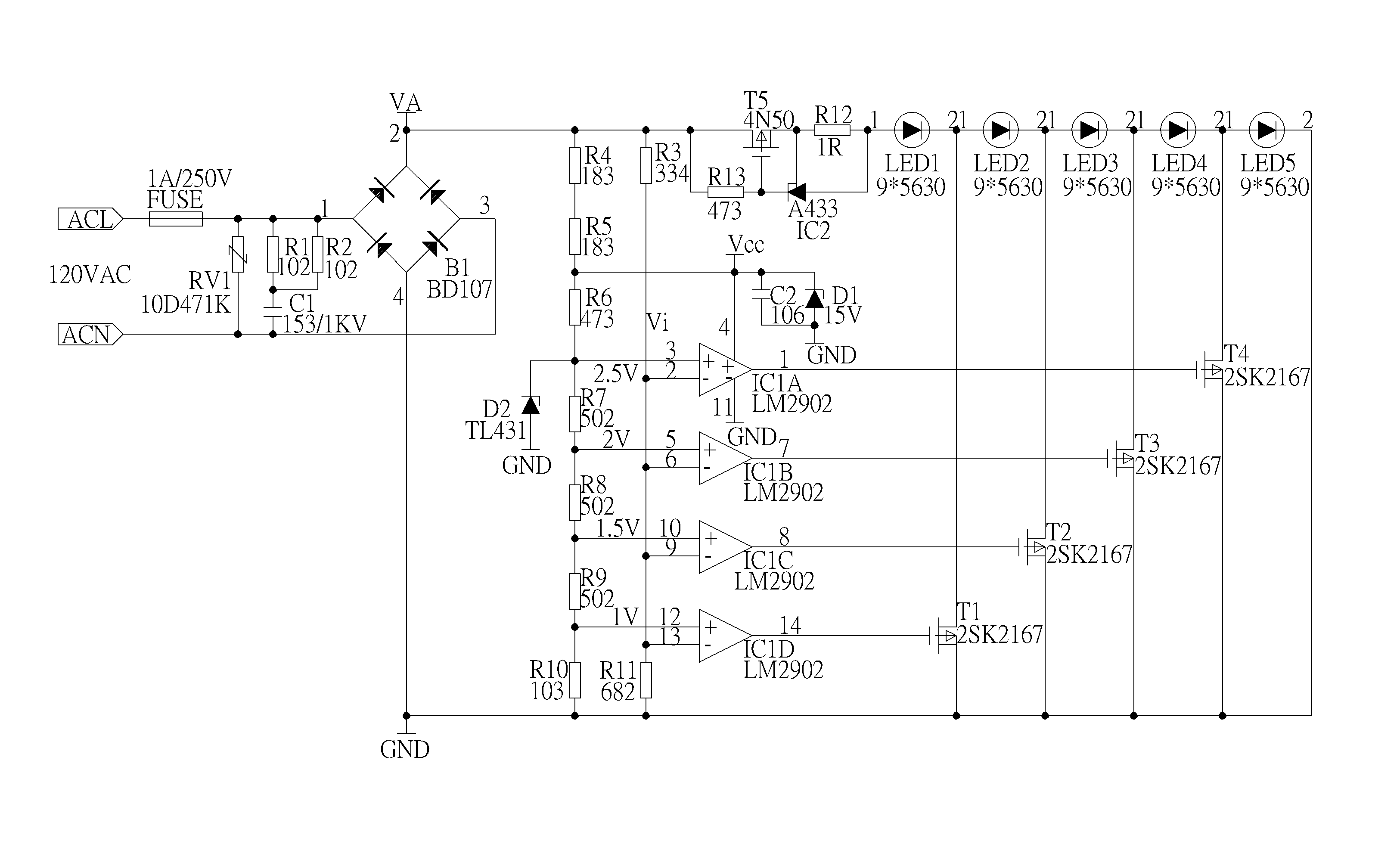
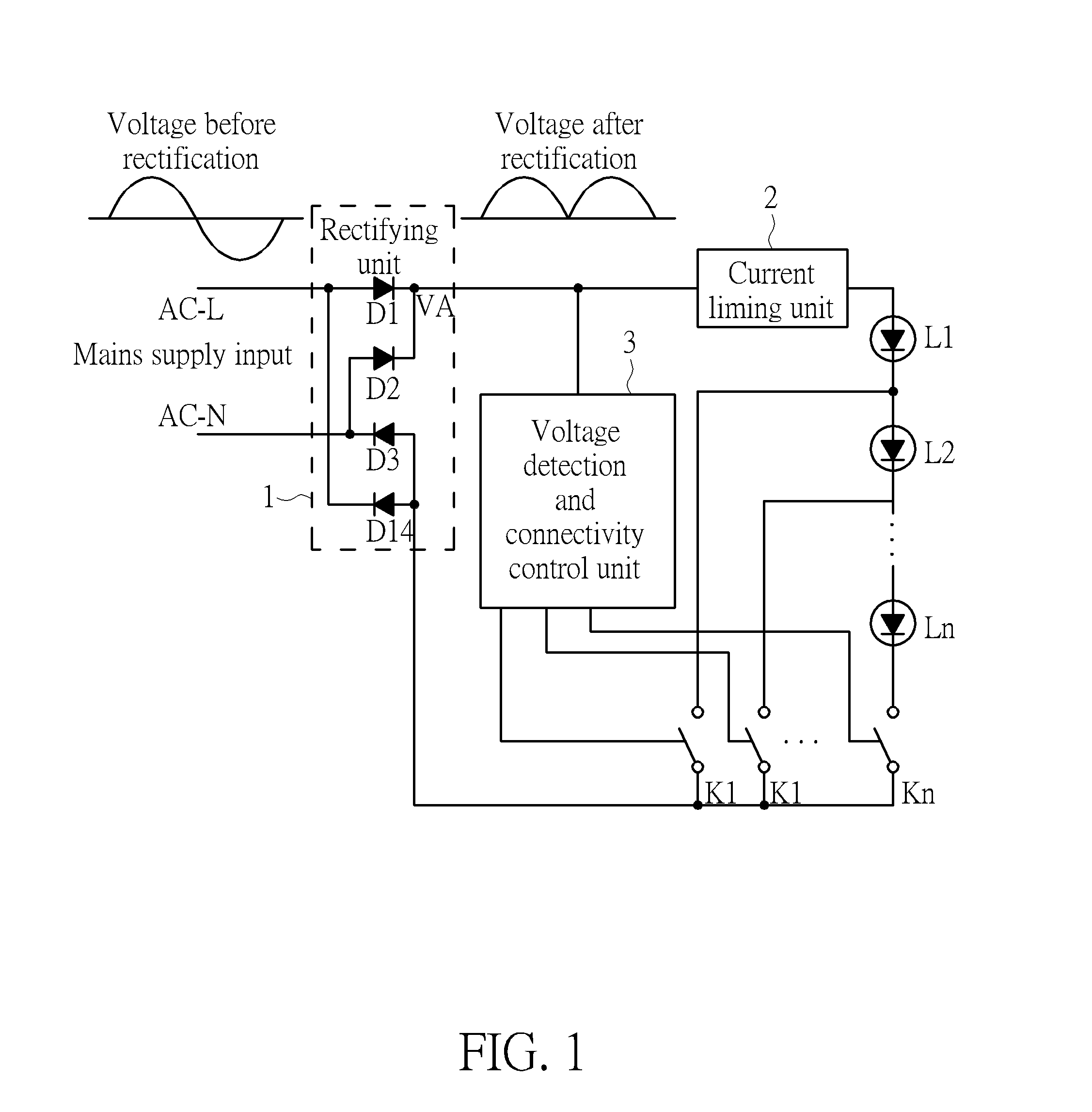
[0037]FIG. 1 shows an LED lamp with a self-adaptive drive circuit. The LED lamp comprises a plurality of series LED lamp strings L1, L2, . . . , Ln, and each LED lamp string comprises a plurality of series LED lamp beads (not shown in the diagram); the self-adaptive drive circuit comprises a rectifying unit 1, a current limiting unit 2, a voltage detection and connectivity control unit 3 and a plurality of controllable switch units K1, K2, . . . , Kn.

[0038]The rectifying unit 1, namely a rectifying circuit consisting of D1-D4 in the diagram, is used for converting an alternating-current voltage output by an alternating-current power supply into a rectified drive voltage.

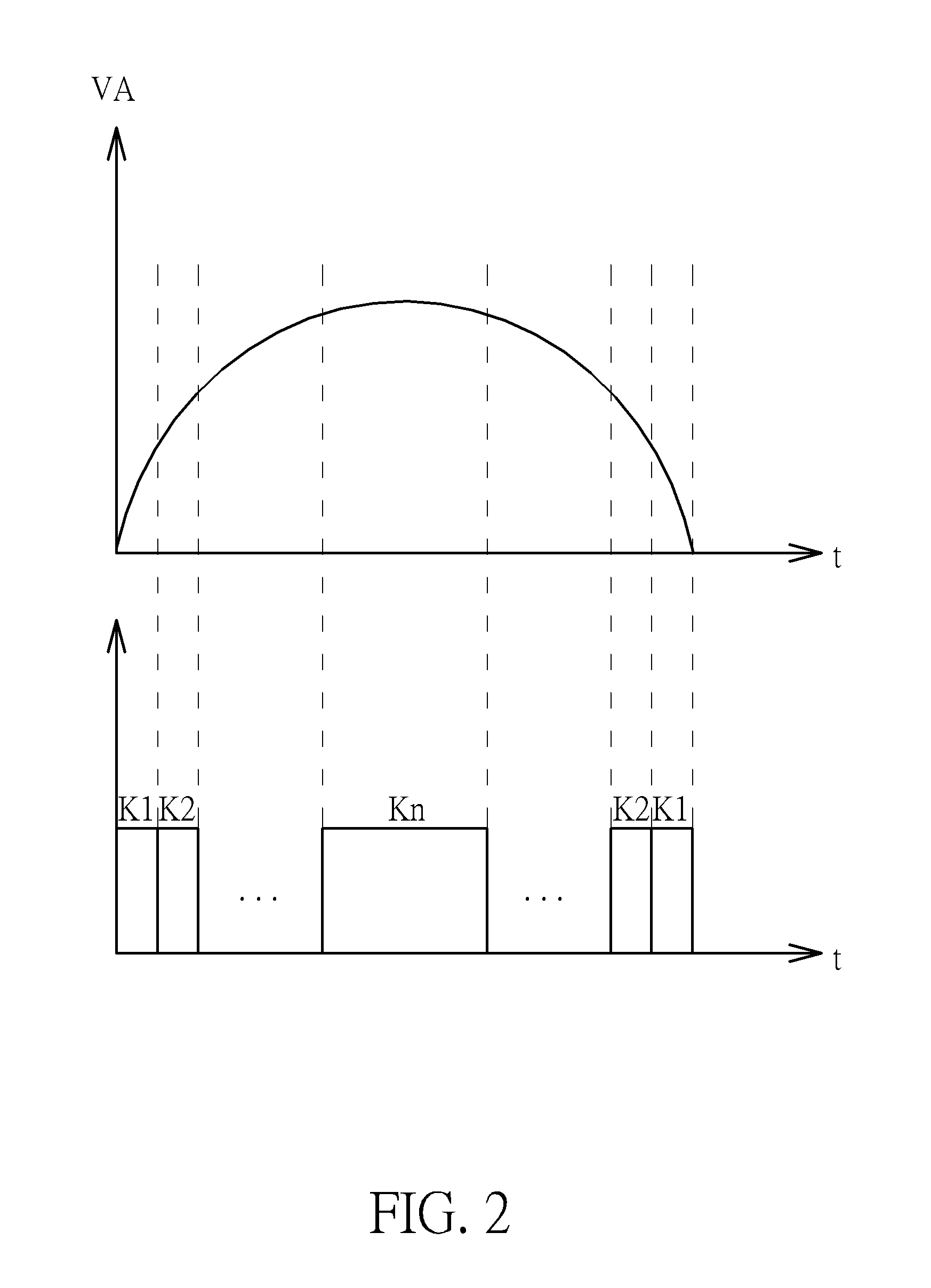
[0039]The voltage detection and connectivity control unit 3 is used for controlling connection / disconnection of the controllable switch units according to the change of the drive voltage, wherein each reference vol...


PUM


Abstract

The invention relates to a technical field of light emitting diodes (LEDs), in particular to a self-adaptive drive circuit and an LED lamp with the same. The LED lamp comprises a plurality of series LED lamp strings, and each LED lamp string comprises at least one series LED lamp bead; and the self-adaptive drive circuit comprises a rectifying unit, a current limiting unit, a voltage detection and connectivity control unit and at least one controllable switch unit. According to the self-adaptive drive circuit and the LED lamp with the same, the LEDs can be driven normally in an extremely simple drive mode, which can work without using complex constant current drive circuit and electrolytic capacitor that is life limiting. At the same time, the stroboflash phenomenon is eliminated, the power factor is improved, harmonic distortion is reduced, electromagnetic interference is eliminated, and the cost is reduced.

Description

BACKGROUND OF THE INVENTION[0001]1. Field of the Invention[0002]The invention relates to a technical field of light emitting diodes (LEDs), in particular to a self-adaptive drive circuit and an LED lamp with the same.[0003]2. Description of the Prior Art[0004]LED, having high luminous efficiency, long service life, solid light source, without polluting heavy metal elements, and other remarkable advantages, is now becoming a new generation of light source and leading a third illumination revolution after the incandescent lamps and the fluorescent lamps.[0005]LED (light emitting diode) has electrical features similar to those of a diode, which is a constant voltage device and is very sensitive to an applied working voltage, and the I / V thereof is in a relation of exponential rise. Generally, the LED can work normally by incorporating a drive power supply that can provide a current-limiting function or a constant current function, and the input mains supply is converted to the constant...

Claims


Application Information

Patent Timeline
Patent Type & Authority Patents(United States)
IPC IPC(8): H05B33/08H05B44/00
CPCH05B33/0824H05B45/44
Inventor PAN, WEIXIONG
Owner GUANGZHOU PLEMAS LIGHTING CO LTD
Learn More