Test glass changing system

a technology of changing system and test glass, which is applied in the direction of instruments, ion implantation coatings, coatings, etc., can solve the problem of complex loading of test glass changers

Inactive Publication Date: 2015-10-13
LEYBOLD OPTICS
View PDF15 Cites 2 Cited by
  • Summary
  • Abstract
  • Description
  • Claims
  • Application Information

AI Technical Summary

Benefits of technology

[0006]According to this, the test glass changing system comprises a test glass holder with a test glass plate for holding one or more test glasses and a cover, which covers the test glass plate and protects the test glasses held therein from being coated. The cover is provided with a measurement window, which only exposes a small region of the test glass plate to being coated. Provision can also be made for a plurality of measurement windows and / or reference windows. The test glass plate can be rotated with respect to the cover by means of a rotation device, which forms a part of the test glass changing system; this moves different test glasses attached to the test glass plate into the region of the measurement window, where they are coated and measured. Compared to the generic DE 36 04 624 A1, the test glass changing system according to the invention differs in that the test glass holder (with the test glass plate and the cover) forms a closed unit that—like the substrates to be coated—can be introduced into the coating chamber through the substrate lock and can be positioned on the rotary disk. This allows a particularly simple and time-saving loading of the rotary disk: instead of equipping the test glass changing system (which is fixedly connected to the rotary disk) with test glasses, as necessary in DE 36 04 624 A1, which test glasses must be introduced individually though the substrate lock and have to be positioned on the test glass plate there, use of the test glass changing system according to the invention allows the equipping and preparation of the test glass holder to be carried out outside of the coating chamber and temporally independently of the substrate change. This is advantageous from an ergonomic point of view and saves time. Furthermore, it is possible to arrange a comparatively large number of test glasses on the test glass holder.
[0009]The lift / rotation device can be arranged in a stationary fashion in the processing chamber and can for example be located in the region of the coating station. In this case, a test glass change can only take place in a prescribed rotational position of the rotary disk, to be precise when the test glass holder is exactly above the lift / rotation device. Alternatively, the test glass rotation device can be arranged on the rotary disk (or on a revolving stage rotating in synch with the rotary disk); the advantage of this is that the test glass change can take place without changing the speed of the rotary disk and at any position in the coating chamber (for example during the transport of the test glass holder between measurement station and coating station).

Problems solved by technology

However, loading the test glass changer is very complicated because the individual test glasses must be inserted into the holder of the test glass changer through the substrate lock.

Method used


Image

  • Test glass changing system
  • Test glass changing system
  • Test glass changing system

Examples


Embodiment Construction

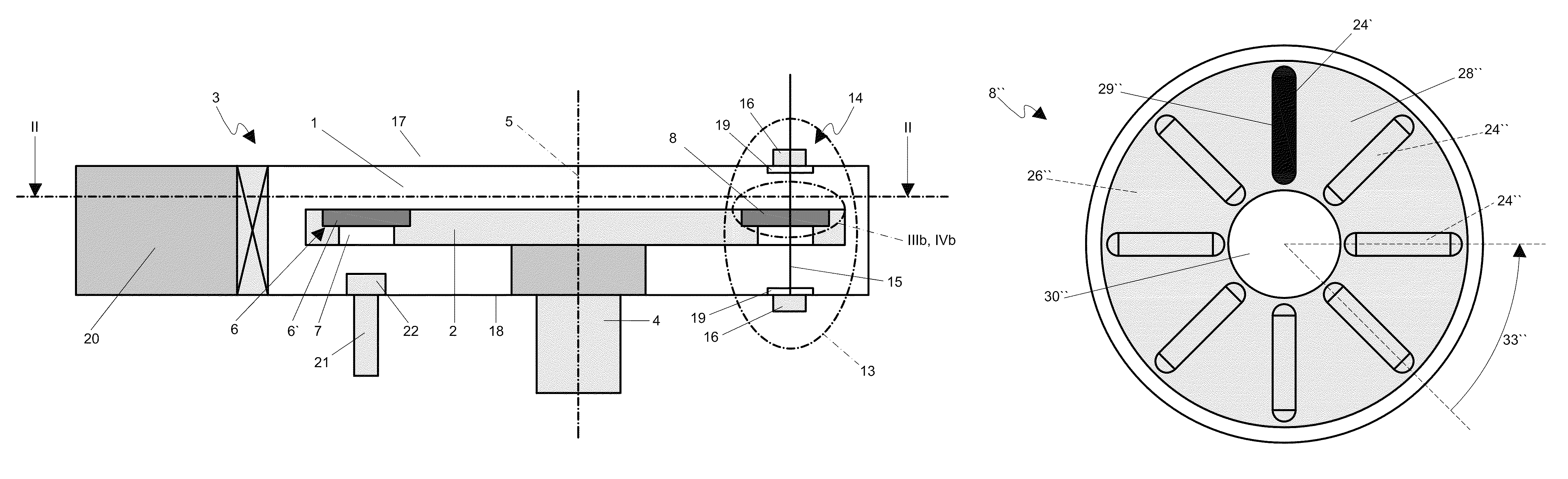
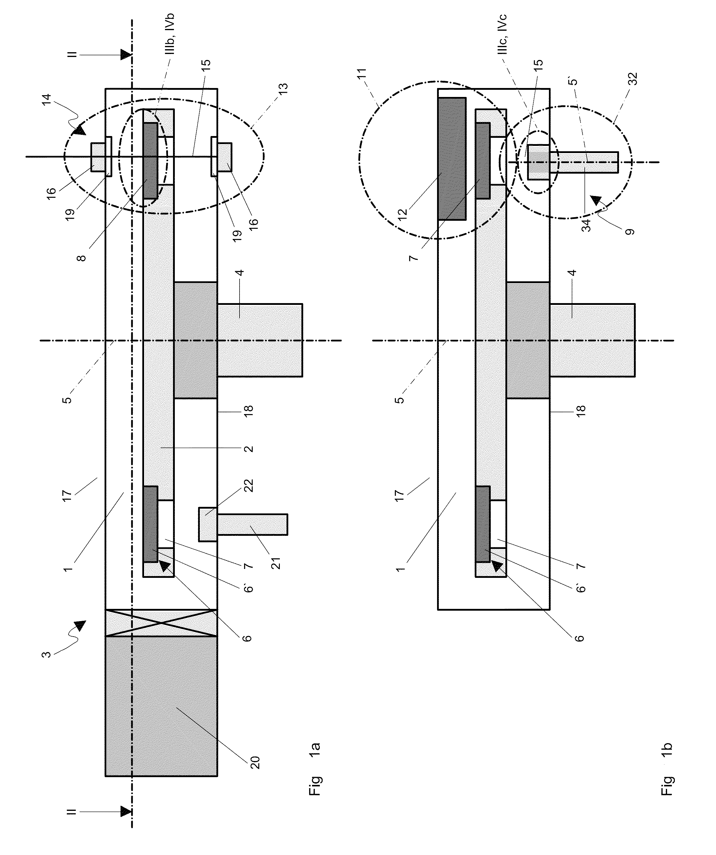
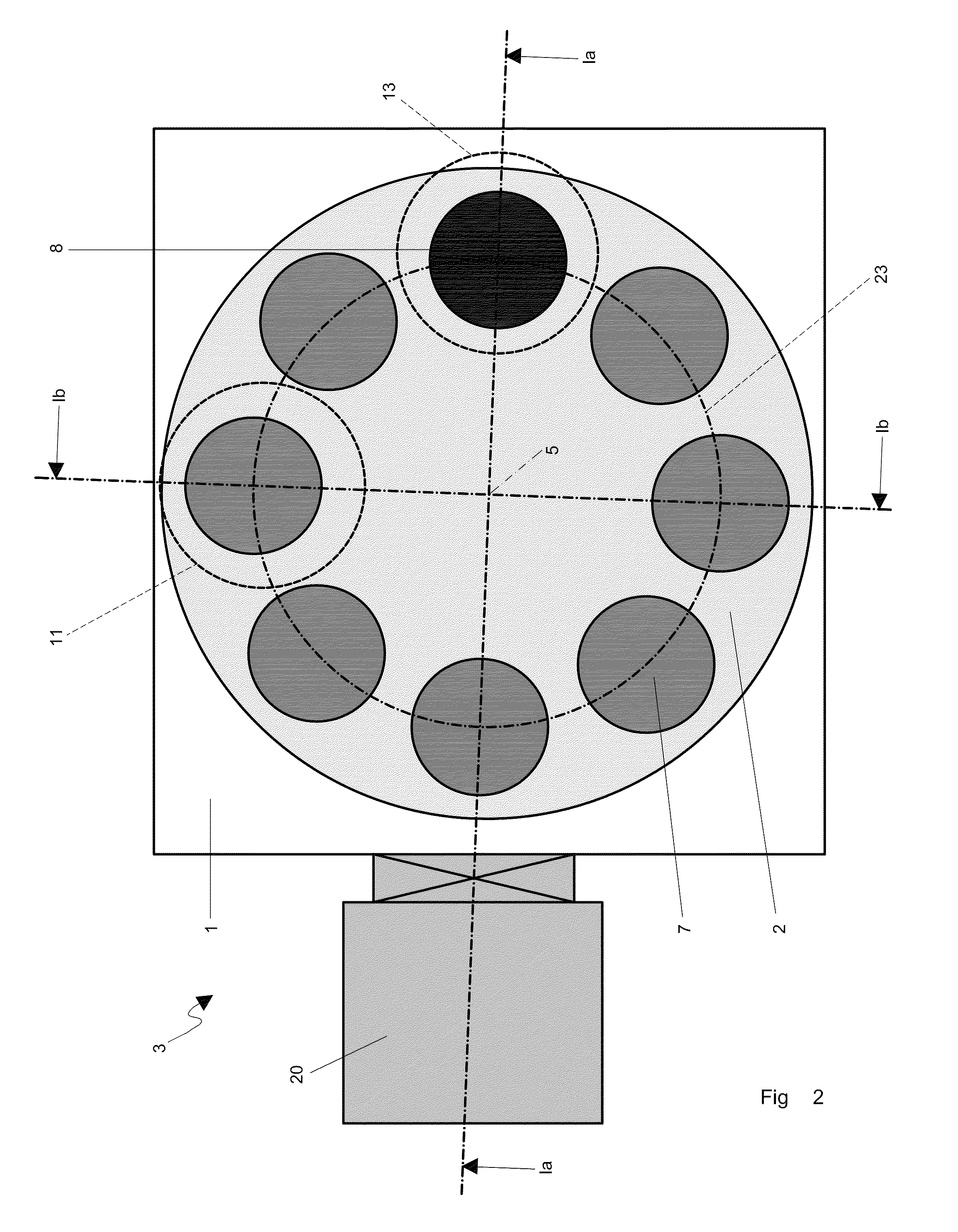
[0023]FIGS. 1a and 1b show schematic sectional views through a coating chamber 1, which forms part of a vacuum coating installation 3. Within the coating chamber 1 there is a rotary disk 2, which can be rotated around a rotational axis 5 with the aid of a rotation apparatus 4 that can be subject to open-loop or closed-loop control. A plan view of the rotary disk 2 is illustrated in FIG. 2. A plurality of recesses 6 are provided on the rotary disk 2, which recesses are arranged on a common great circle 23 around the axis 5. The recesses 6 can selectively be equipped with a disk-shaped substrate 7 or with a test glass holder 8; an oxide layer is deposited under residual gas on these substrates 7 and on the test glass holder 8 in the coating chamber 1. Together with a test glass rotation device 9, the test glass holder 8 forms part of a test glass changing system 10.

[0024]The rotary disk 2 is equipped with substrates 7 or test glass holder 8 through a substrate lock 20 in a side wall o...


PUM

PropertyMeasurementUnit
diameteraaaaaaaaaa
diameteraaaaaaaaaa
widthaaaaaaaaaa

Abstract

The invention relates to a test glass changing system (10) for selectively coating and optically measuring a test glass (24, 24″) in a coating chamber (1) of a vacuum coating installation (3). In the coating chamber, a movable turntable (2) is used to guide substrates (7) on a path through a stream of a coating material. The test glass changing system (10) comprises a test glass holder (8, 8″) with a test glass plate (26) for holding the test glass (24, 24″), and a cover (28, 28″) for selectively covering the test glass plate (26). The test glass changing system (10) also comprises a rotary apparatus (34) for rotating the test glass plate (26) about an axis (51) which is oriented approximately parallel to the axis of rotation (5) of the turntable (2). The test glass holder (8, 8″) can be positioned on the turntable (2) and removed from the coating chamber (1) in the form of a unit.

Description

TECHNICAL FIELD[0001]The invention relates to a test glass changing system for selectively coating and optically measuring a test glass plate in a vacuum coating installation.BACKGROUND[0002]The production of optical multilayer systems, which are also referred to as interference layers, plays an important role in, for example, optical products such as band-pass filters, edge filters, cold mirrors, beam splitters, and antireflection coatings. The goal of such a coating is to achieve transmission or reflection at the multilayer system that is as complete as possible within a prescribed wavelength range but achieve negligible transmission or reflection in the wavelength ranges outside thereof, with the smallest transition region possible. Meeting these demands requires a large number of individual layers, wherein, for example, layers with high and low refractive index are alternately applied to the substrate; however, it is also possible for two layers with a high refractive index or t...

Claims


Application Information

Patent Timeline
Patent Type & Authority Patents(United States)
IPC IPC(8): G01B11/06C23C14/54C23C14/56C23C14/04C23C14/50
CPCC23C14/547C23C14/042C23C14/50G01B11/0683C23C14/566G01B11/0616C23C14/56C23C14/54
Inventor SCHERER, MICHAEL
Owner LEYBOLD OPTICS
Why Eureka
Try Eureka