Method for producing conductive segment

a technology of conductive segments and conductive segments, which is applied in the direction of conductors, instruments, machines/engines, etc., can solve the problems of poor conduction, measurement cannot be performed, and incorrect values may be obtained, and achieve the effect of ensuring deterioration resistance and corrosion resistance and high reliability

Inactive Publication Date: 2015-10-13
YAZAKI CORP
View PDF16 Cites 0 Cited by
  • Summary
  • Abstract
  • Description
  • Claims
  • Application Information

AI Technical Summary

Benefits of technology

[0017]The present invention has been made in view of the above circumstances, and has an object to provide a method for producing a conductive segment capable of securing deterioration resistance and corrosion resistance in the use in ordinary environment and even in the used in the presence of a sulfur component such as gasoline, and giving high reliability to a detection value even in the case of using in, for example, a liquid level detector, and a conductive segment produced by the production method.
[0029]According to the present invention, by burning an Ag—Pd conductive paste and an Au conductive paste laminated, silver and palladium contained in the Ag—Pd conductive paste diffuse into a region formed by the Au conductive paste, and gold contained in the Au conductive paste diffuses into a region formed by the Ag—Pd conductive paste. As a result, conductivity and abrasion resistance of the whole conductive segment are improved, and even though an insulating material is formed by sulfurization of the conductive segment itself or sulfurization of an abrasion powder generated by the sliding between conductive segments and contacts, increase in a resistance value and disturbance of output waveform can be suppressed.
[0030]Therefore, for example, when the conductive segment is used in a liquid level detector, a detection value can be obtained with high reliability. Furthermore, even in the use of the conductive segment in gasoline containing a large amount of sulfur components and fuels having various formulations, the conductive segment has sufficient deterioration resistance and corrosion resistance. In addition, gold (Au) is not required to use in a large amount, leading to low-cost production.
[0031]According to another present invention, by burning an Ag—Pd conductive paste and an Au conductive paste that were laminated, silver and palladium contained in the Ag—Pd conductive paste diffuse into a region formed by the Au conductive paste, gold contained in the Au conductive paste diffuses into a region formed by the Ag—Pd conductive paste, and the gold (Au) content becomes nearly uniform in a range of 30% or more from a surface layer to the vicinity of an intermediate layer in the conductive segment. As a result, the gold (Au) attaches to a contact that slides, thereby suppressing sulfurization, oxidization and corrosion of silver (Ag), and contact conduction between the contact and the conductive segment becomes good.
[0032]Accordingly, conductivity and abrasion resistance of the whole conductive segment are improved, and even though an insulating material is formed by sulfurization of the conductive segment itself and sulfurization of an abrasion powder generated by the sliding between the conductive segment and the contact, the increase in a resistance value and disturbance of output waveform can be suppressed.
[0033]Therefore, for example, when the conductive segment is used in a liquid level detector, a detection value can be obtained with high reliability. Furthermore, even in the use of the conductive segment in gasoline containing a large amount of sulfur components and fuels having various formulations, the conductive segment has sufficient deterioration resistance and corrosion resistance. In addition, gold (Au) is not required to use in a large amount, leading to low-cost production.

Problems solved by technology

However, contacts and conductive segments deteriorate or corrode by sulfur content, moisture, alcohol content and the like in a fuel, resulting in poor conduction.
As a result, drawbacks such that measurement cannot be performed and incorrect values are obtained may occur.
This increases a resistance value and causes turbulence of output waveform, leading to deterioration of reliability of a liquid level detector.
However, in the inventions disclosed in PTL 1 and 2, the thickness of the covering layer of an alloy containing gold (Au) is decreased with the passage of time; therefore, effectiveness of the effect may not be sufficient.
Furthermore, the inventions disclosed in PTL 1 and 2 had the problem that gold (Au) must be contained in a large amount in order to secure sufficient deterioration resistance and corrosion resistance, and this led to the problem of increase in costs.
Meanwhile, the conventional technologies disclosed in PTL 3 have effectiveness to corrosion and sulfurization, but have the problems that the effectiveness is not sufficient, and a large amount of gold (Au) is used, leading to the increase in costs.

Method used


Image

  • Method for producing conductive segment
  • Method for producing conductive segment
  • Method for producing conductive segment

Examples


first embodiment

(First Embodiment)

[0051]Now, referring to the drawings, a method for producing a conductive segment, and a conductive segment according to the first embodiment of the present invention will be described in detail. Fundamental structure regarding a liquid level detector is described in detail in the description of the prior art of the present specification by reference to FIGS. 1, 2 and 3, but is again described below.

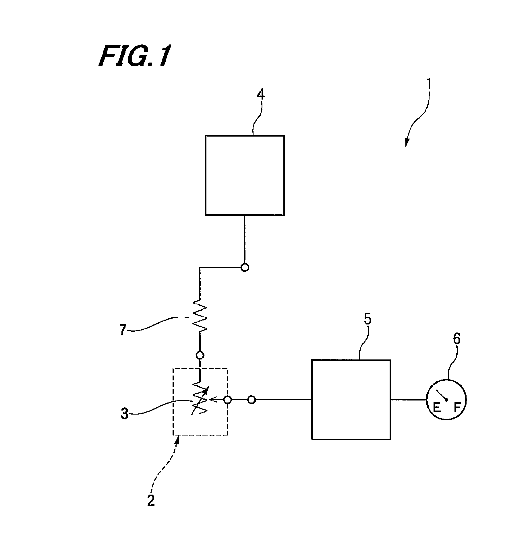
[0052]As shown in FIG. 1, a sensor 2 of a liquid level detector 1 is equipped with a variable resistor 3 changing a resistance value in the course of movement of contacts 19 and 20 described hereinafter in conjunction with height transition of a liquid level in the inside T of a fluid tight vessel, and the variable resistor 3 is connected to a fixed resistor 7 in series and connected to a power circuit 4 applying a given voltage to the variable resistor 3 and the fixed resistor 7.

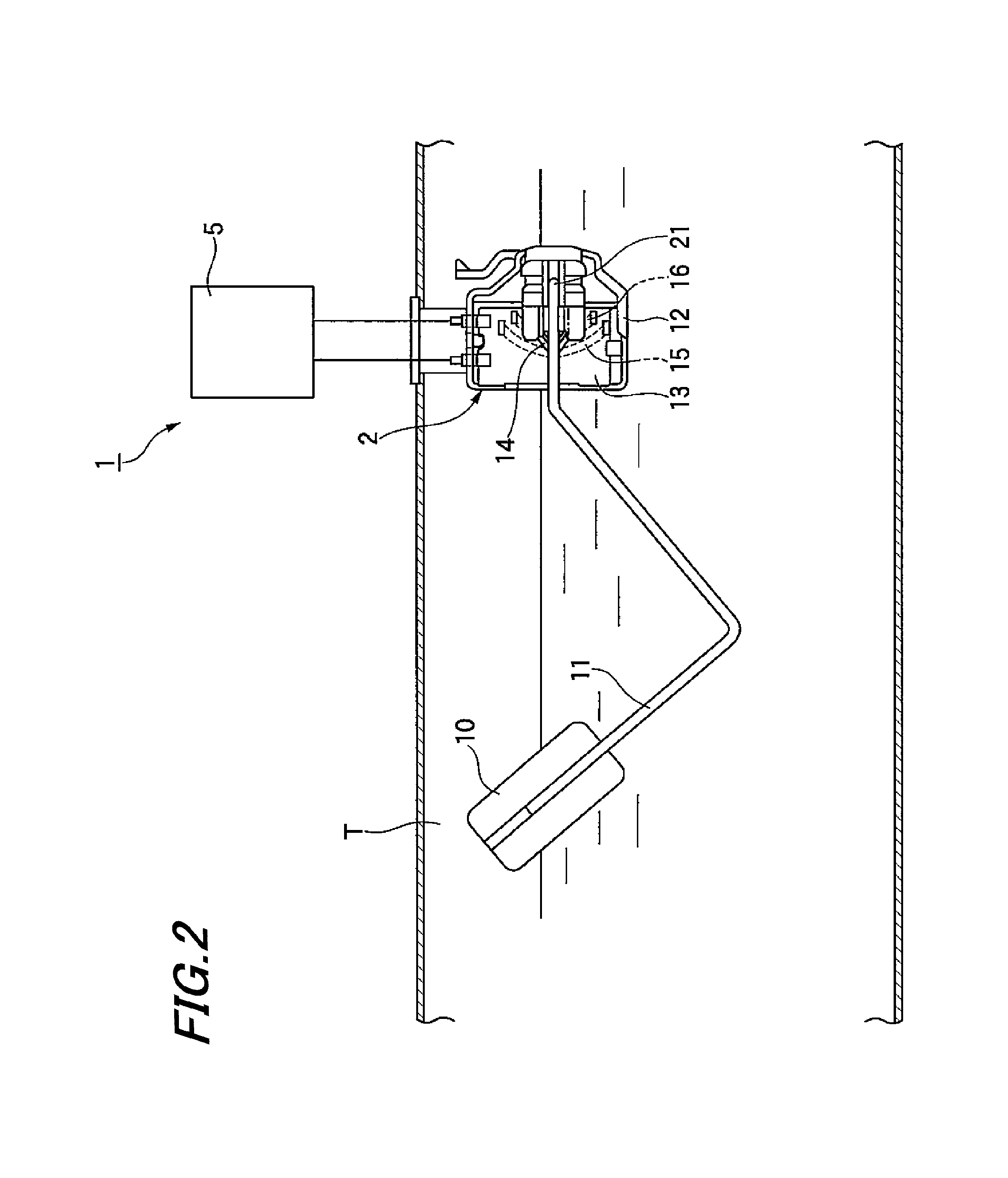
[0053]As shown in FIG. 2 and FIG. 3, the sensor 2 includes a body frame 12, a resistance pl...

second embodiment

(Second Embodiment)

[0108]Now, referring to the drawings, a method for producing a conductive segment, and a conductive segment according to the second embodiment of the present invention will be described in detail. The components which are substantially identical with or similar to those of the first embodiment are denoted by the same reference numerals, and duplicated description is omitted.

[0109]In this embodiment of the present invention, the conductive segment is constituted of a metal conductive material containing at least silver (Ag) and palladium (Pd), and a metal conductive material comprising gold (Au) as a main component.

[0110]The amounts of various metals added in the metal conductive material containing at least silver (Ag) and palladium (Pd) (hereinafter referred to as “Ag—Pd conductive paste”) can appropriately be determined, giving consideration to designed values of amounts of metals in a conductive segment finally obtained. For example, it is preferred in the Ag—P...


PUM

PropertyMeasurementUnit
temperatureaaaaaaaaaa

Abstract

A method for producing a conductive segment, includes: a step of printing a metal conductive paste on a substrate, and drying the paste; a step of printing other metal conductive paste on the metal conductive paste after drying, and drying the paste; and a step of burning the metal conductive paste after drying and the other metal conductive paste after drying, wherein the conductive metal paste is an Ag—Pd conductive paste comprising silver (Ag) and palladium (Pd), and the other metal conductive paste is an Au conductive paste comprising gold (Au) as a main component; or the metal conductive paste is an Au conductive paste comprising gold (Au) as a main component, and the other metal conductive paste is an Ag—Pd conductive paste comprising silver (Ag) and palladium (Pd).

Description

BACKGROUND OF THE INVENTION[0001]The present invention relates to a method for producing a conductive segment, and a conductive segment. More particularly, the invention relates to a method for producing a conductive segment used as an electrode of a resistance plate of a liquid level detector detecting a liquid level height of a transportation fuel tank of automobiles, aircraft and the like, and a conductive segment produced by the production method.[0002]A liquid level detector in which a float arm slides on a resistance plate by a float moving up and down according to a liquid level is conventionally known as a liquid level detector detecting a liquid level height of a fuel tank of, for example, automobiles.[0003]One example of a liquid level detector is described below. FIG. 1 is an electrical block diagram for explaining a structural example of a sensor used in a liquid level sensor. FIG. 2 is an explanatory view for explaining a structural example of a liquid level detector. F...

Claims


Application Information

Patent Timeline
Patent Type & Authority Patents(United States)
IPC IPC(8): B05D5/12C22C5/02H01C17/28H01C1/142G01F23/36C22C5/06B05D7/00B05D3/02B32B15/01
CPCG01F23/36C22C5/02C22C5/06H01C1/142H01C17/281Y10T428/12889B05D3/02B05D5/12B05D7/50B32B15/01
Inventor OIKE, TOSHIOTANAKA, KENICHIHIROSE, RYOSHIMIZU, TAKAFUMI
Owner YAZAKI CORP
Why Eureka
Try Eureka