
Fiber reinforced resin, manufacturing method for fiber reinforced resin, and manufacturing system for fiber reinforced resin

a manufacturing method and fiber reinforced resin technology, applied in the direction of synthetic resin layered products, transportation and packaging, chemistry apparatus and processes, etc., can solve the problems of uneven quality of fiber reinforced resin, excessive or insufficient resin injection amount, and deterioration of strength and dimensional accuracy of products, so as to suppress uneven quality of products and high strength and dimensional accuracy

Inactive Publication Date: 2015-10-20
TOYOTA JIDOSHA KK
View PDF32 Cites 0 Cited by
  • Summary
  • Abstract
  • Description
  • Claims
  • Application Information

AI Technical Summary

Benefits of technology

This approach enables the production of fiber reinforced resin with high strength and dimensional accuracy, while minimizing quality unevenness and preventing sunk spots, thereby enhancing the consistency of the manufacturing process.

Problems solved by technology

In the technique described in JP-A-2005-271551, only an amount of resin equivalent to a product is injected, so the injected amount of resin tends to be excessive or insufficient.
This tends to cause unevenness in quality of fiber reinforced resin.
This deteriorates the strength and dimensional accuracy of the product.

Method used


Image

  • Fiber reinforced resin, manufacturing method for fiber reinforced resin, and manufacturing system for fiber reinforced resin
  • Fiber reinforced resin, manufacturing method for fiber reinforced resin, and manufacturing system for fiber reinforced resin
  • Fiber reinforced resin, manufacturing method for fiber reinforced resin, and manufacturing system for fiber reinforced resin

Examples


first embodiment

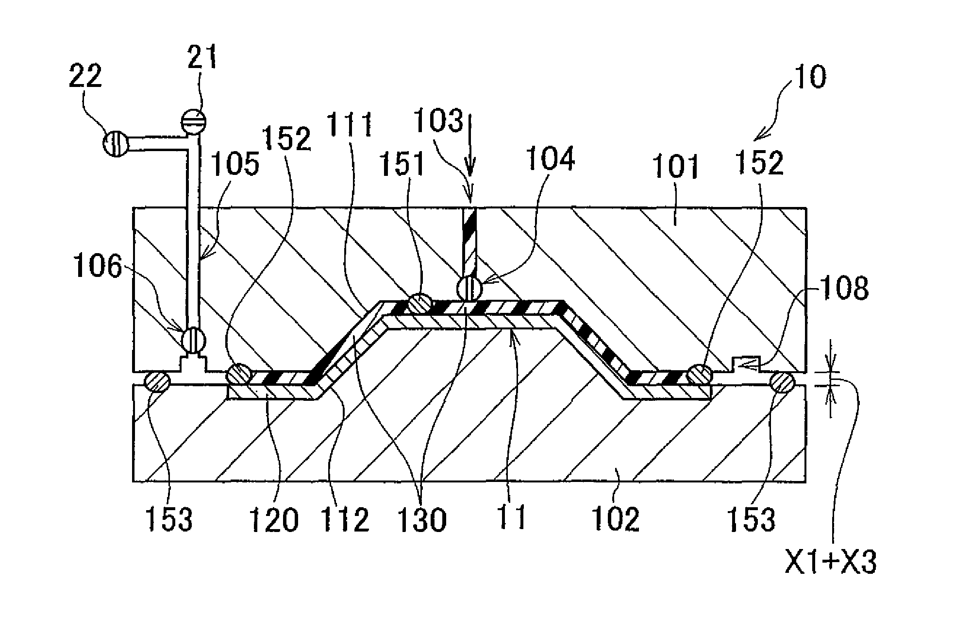
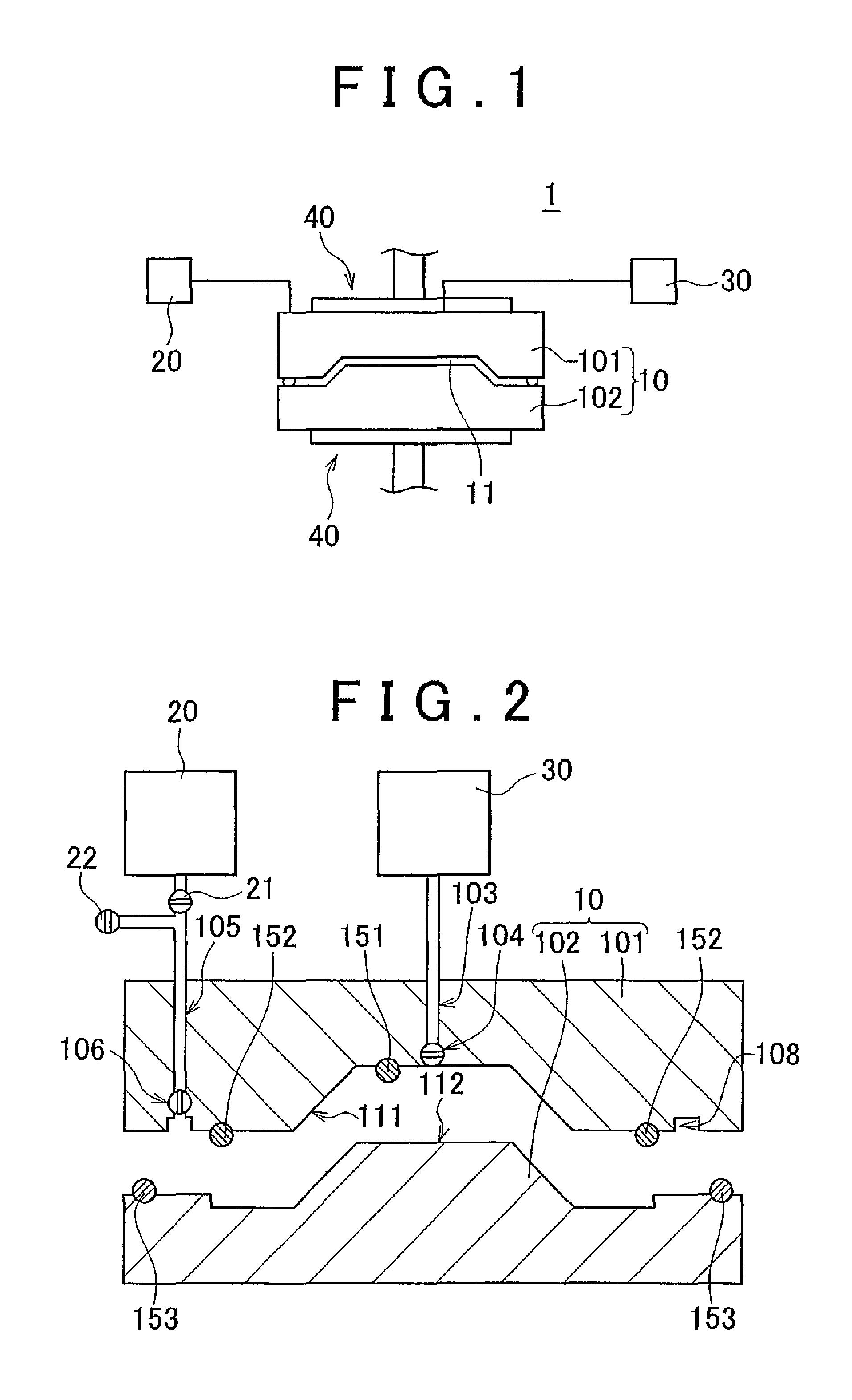
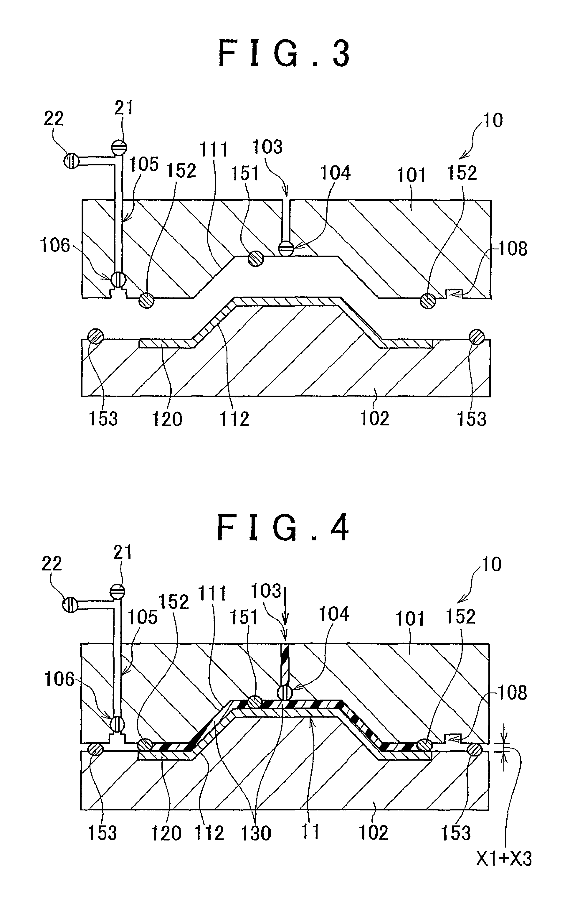
[0030]Hereinafter, the invention will be described with reference to the accompanying drawings. FIG. 1 is a view that shows a manufacturing system 1 for a fiber reinforced resin according to the present embodiment. The manufacturing system 1 includes a molding die 10, a decompressor 20, a resin injector 30, and a die closer 40. The decompressor 20 and the resin injector 30 are connected to the molding die 10. The die closer 40 applies pressure to the molding die 10 in the vertical direction. The molding die 10 includes an upper die 101 and a lower die 102. A cavity 11 is formed between the upper die 101 and the lower die 102. The cavity 11 has a shape corresponding to the shape of a product. The manufacturing system 1 injects resin into the cavity 11 defined by the upper die 101 and the lower die 102, and cures the resin while applying pressure to the resin using the die closer 40, thus molding the injected resin. The die closer 40 includes position adjusting means (not shown) and c...

second embodiment

[0049]In the second embodiment, in the first process, as shown in FIG. 7, a resin diffusion medium 521 is placed on the cavity surface 512 of the lower die 502, and a fiber reinforced base 520 that contains a core material 522 therein is placed on the resin diffusion medium 521. The core material 522 may be, for example, rigid urethane foam or polymethacrylic foam. The fiber reinforced base 520 may be, for example, carbon fiber.

[0050]The resin diffusion medium 521 is placed in order to ensure a space for allowing resin to flow between the fiber reinforced base 520 and the cavity surface 512 of the lower die 502. The resin diffusion medium 521 may be, for example, nylon mesh having a thickness of 0.8 mm and an open area ratio of 80 percent or above.

[0051]When the molding die 50 is used, in the first process, as resin is injected through the resin injection passage 503 formed in the upper die 501, the fiber reinforced base 520 and the core material 522 are pressed against the cavity s...


PUM

PropertyMeasurementUnit
pressureaaaaaaaaaa
thicknessaaaaaaaaaa
draft angleaaaaaaaaaa

Abstract

A first process in which a fiber reinforced base is placed in a cavity of a molding die and then resin is injected into the cavity of the molding die in a state where the molding die is opened by a sum of a distance X1 and a distance at the time of completion of molding; a second process in which the molding die is closed to a state where the molding die is opened by a sum of a distance X2 and the distance at the time of completion of molding while resin in the cavity is being drained; and a third process in which the drain of the resin from the cavity is stopped and then the molding die is closed to the distance at the time of completion of molding while a die clamping pressure is maintained at a predetermined value to cure the resin, are carried out sequentially.

Description

BACKGROUND OF THE INVENTION[0001]1. Field of the Invention[0002]The invention relates to a fiber reinforced resin, a manufacturing method for the fiber reinforced resin, and a manufacturing system for the fiber reinforced resin.[0003]2. Description of the Related Art[0004]A fiber reinforced resin may be manufactured by molding and curing resin containing a fiber reinforced base. In order to manufacture a high-quality fiber reinforced resin, it is necessary to uniformly impregnate resin into a fiber reinforced base. For example, in a technique described in Japanese Patent Application Publication No. 2005-271551 (JP-A-2005-271551), a gap is provided in a cavity of a molding die between a cavity inner surface and a fiber reinforced base, and an amount of resin equivalent to a molded product is injected into the gap. After that, the molding die is closed to narrow the cavity to thereby spread the resin over the fiber reinforced base. In addition, in a technique described in Japanese Pat...

Claims


Application Information

Patent Timeline
Patent Type & Authority Patents(United States)
IPC IPC(8): B29C70/48B29C43/34B29C70/46
CPCB29C70/48B29C43/34B29C70/467B29C2043/3444Y10T428/24994B29C70/547B29C70/865
Inventor KATAHIRA, NATSUHIKOYOSHIMURA, JOJITSUZUKI, MAKOTOYASUE, MASAHIKO
Owner TOYOTA JIDOSHA KK
Learn More