
LED lamp having a cooling body

a technology of led lamps and cooling bodies, which is applied in the direction of point-like light sources, semiconductor devices of light sources, light and heating apparatus, etc., can solve the problems of limited heat dissipation efficiency, and achieve the effect of reliable and effective heat dissipation and particularly effective heat dissipation

Active Publication Date: 2015-10-20
TRIDONIC JENNERSDORF GMBH
View PDF9 Cites 4 Cited by
  • Summary
  • Abstract
  • Description
  • Claims
  • Application Information

AI Technical Summary

Benefits of technology

The patent text describes a new LED lamp that can replace traditional incandescent or halogen lamps without needing any modifications to the luminaire. The LED lamp has the same shape and appearance as a conventional lamp, making it easy to install. The design also improves heat dissipation, making the LED lamp more efficient.

Problems solved by technology

The efficiency of heat dissipation is limited with this heat sink.

Method used


Image

  • LED lamp having a cooling body
  • LED lamp having a cooling body
  • LED lamp having a cooling body

Examples


Embodiment Construction

[0041]FIG. 10 shows a sketch of a side view of an LED lamp L according to the invention. The LED lamp L has a heat sink K6 according to the invention in accordance with an exemplary embodiment. In particular, different heat sinks K1-K6 for LED lamps will be described below using different exemplary embodiments.

[0042]The LED lamp L can be designed such that it is suitable as a replacement for a conventional incandescent bulb or halogen lamp. Therefore, in terms of its external appearance, it can have substantially the shape of a conventional incandescent bulb or halogen lamp and / or be equipped with a corresponding thread 40, or an E27 or E14 thread, or a plug (not shown), which thread or plug is used for mechanical and electrical connection to a corresponding conventional lampholder. Such a lamp is therefore often also referred to as a “retrofit LED lamp”.

[0043]To be more precise, a supply circuit (“driver circuit”) T is supplied with voltage starting from the base or plug, said volt...


PUM


Abstract

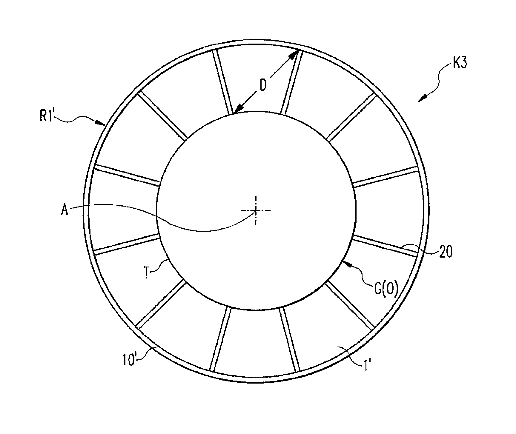
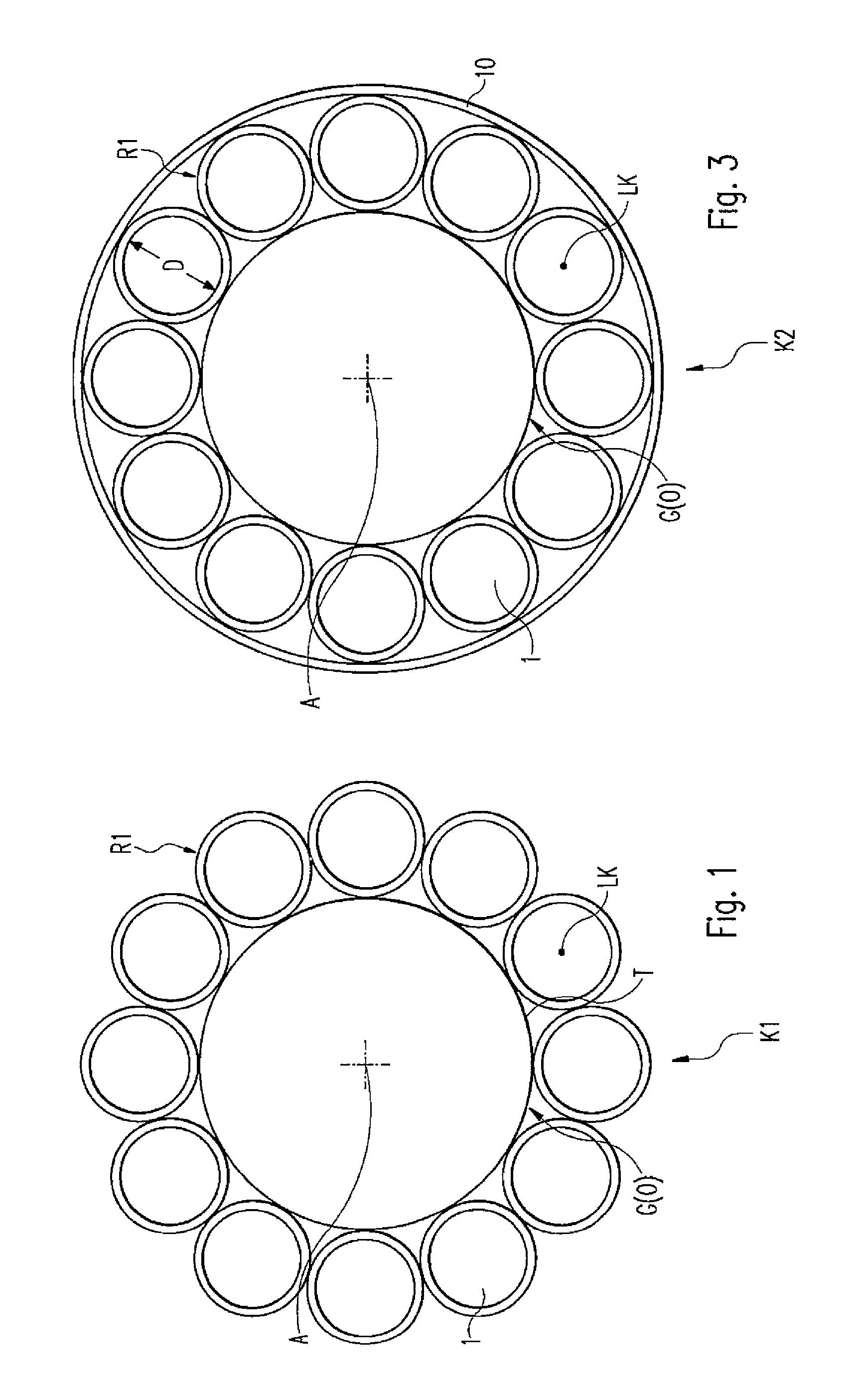
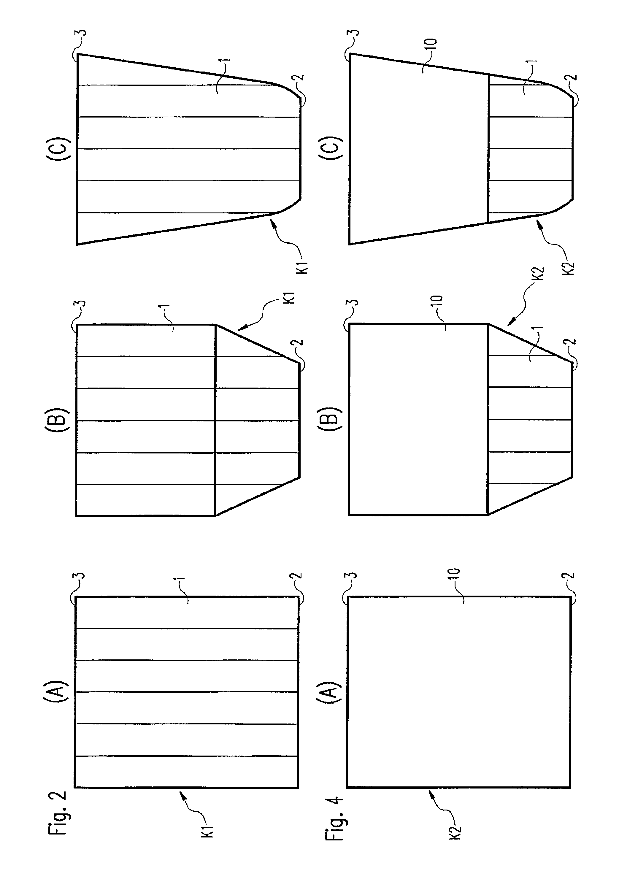
The invention relates to an LED lamp (L), having a light-emitting means with at least one LED, and a heat sink (K1-K6), characterized in that the heat sink (K1-K6) is configured such that a plurality of channels (1, 1′, 1″, 1′″) are formed through said heat sink for transporting away air which is heated by operation of the light-emitting means, wherein the channels (1, 1′, 1″, 1′″) are arranged in the form of a ring around an axis (A), and wherein the length of at least one channel (1, 1′, 1″, 1′″) is at least half the shortest diagonal or transversal in the transverse extent of the corresponding one channel. The arrangement according to the invention and in particular the configuration of the channels (1, 1′, 1″, 1′″) make it possible to achieve particularly effective dissipation of heat.

Description

BACKGROUND OF THE INVENTION[0001]The invention relates to an LED lamp (LED: light-emitting diode), which comprises a light-emitting means with at least one LED and a heat sink.[0002]During operation of an LED lamp, in principle heat is generated, to be precise by the LED or LEDs themselves, but also by a supply circuit (“driver circuit”) for the LED(s). This heat is at least partially transferred from said components to surrounding components or the surrounding air. In order to enable as high an efficiency of the lamp as possible, colour stability, possibly colour temperature stability in the case of white LEDs and as long a life of the LED(s) as possible, it is desirable for the heat to be transported away from said components (supply circuit, LED chip) effectively and efficiently, with the result that the temperature of the LED does not rise beyond a certain extent.[0003]The prior art WO 2006 / 118457 A1 has disclosed a heat sink for an LED lamp. The efficiency of heat dissipation i...

Claims


Application Information

Patent Timeline
Patent Type & Authority Patents(United States)
IPC IPC(8): F21V29/00F21K99/00F21V29/77F21V29/83F21Y101/02
CPCF21V29/004F21K9/135F21V29/773F21V29/83F21Y2101/02F21K9/232F21Y2115/10F21K9/00
Inventor BAKK, ISTVAN
Owner TRIDONIC JENNERSDORF GMBH
Learn More