Information code and information code reading apparatus
a technology of information code and reading apparatus, applied in the direction of instruments, sensing record carriers, sensing by electromagnetic radiation, etc., can solve the problem of inability to detect fraudulent codes, and achieve the effect of facilitating authenticity determination
- Summary
- Abstract
- Description
- Claims
- Application Information
AI Technical Summary
Benefits of technology
Problems solved by technology
Method used
Image
Examples
first embodiment
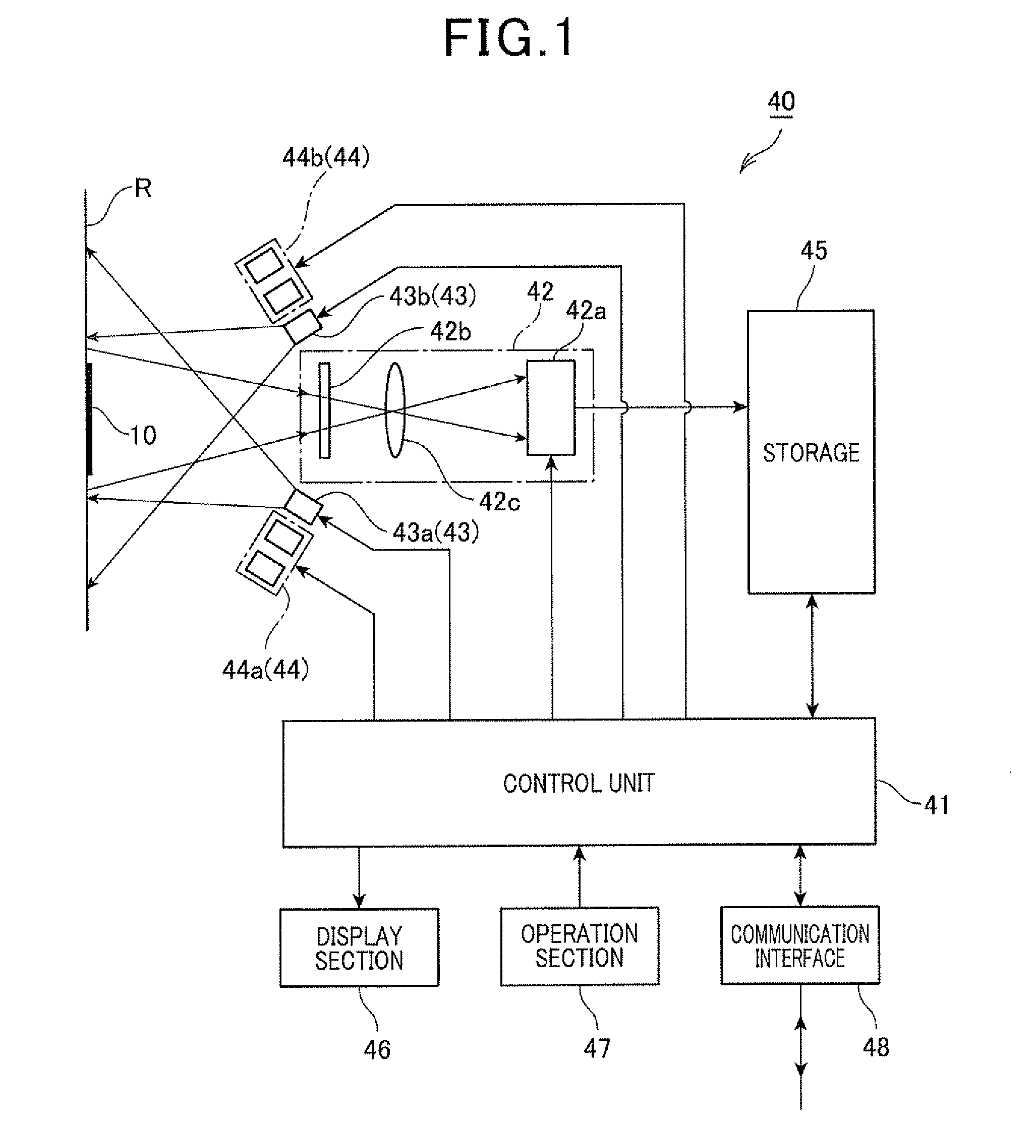
[0054]Referring to FIGS. 1 to 4, first, a first embodiment is described. FIG. 1 is a schematic block diagram illustrating a principal part of an information code reading apparatus 40 that reads an information code 10, according to the first embodiment.
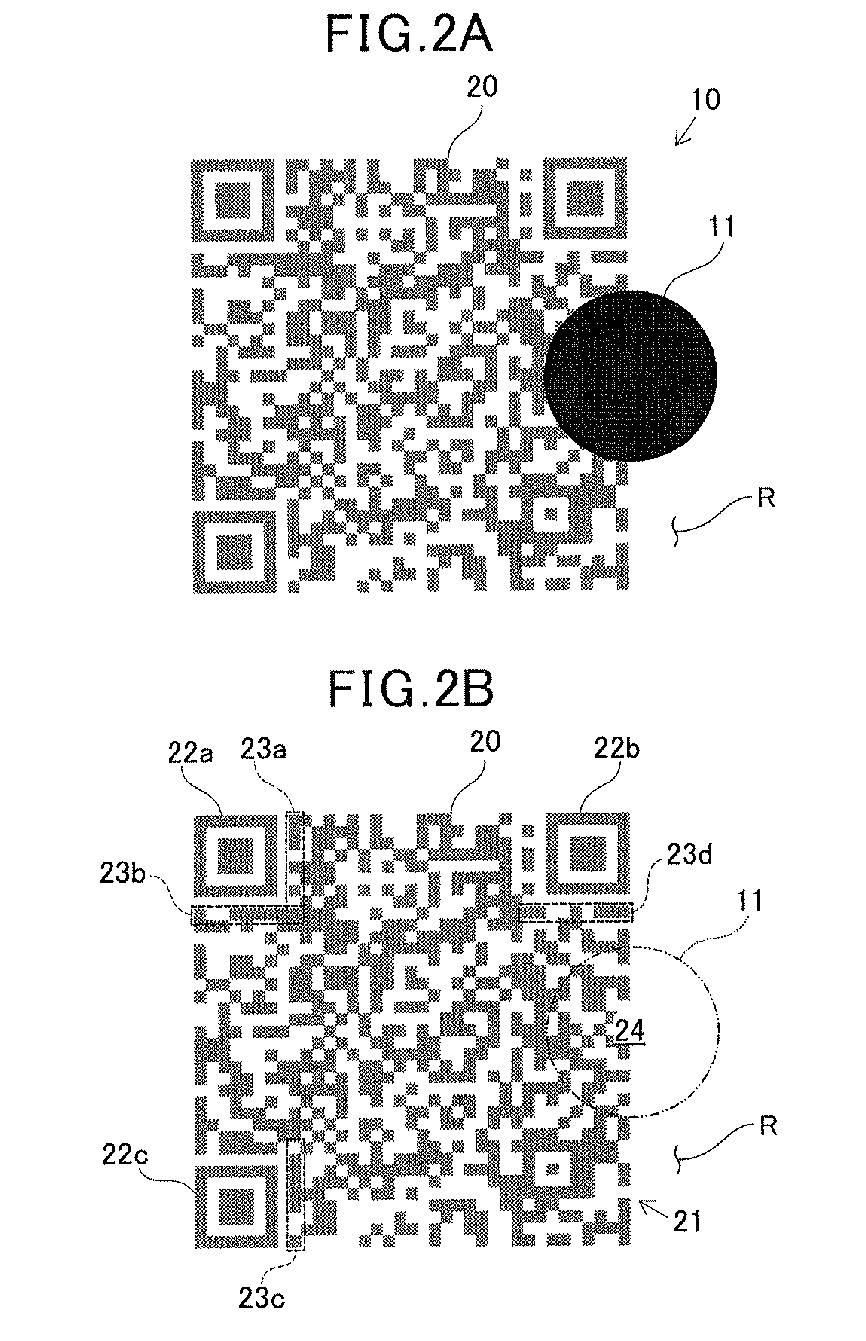
[0055]The information code reading apparatus 40 shown in FIG. 1 is configured to optically read generally used information codes or information codes 10 composed of modules and having a configuration characteristic of the present invention. Generally used information codes include one-dimensional codes (e.g., bar codes) and two-dimensional codes (e.g., QR Codes™, data matrix codes, MaxiCodes, Aztec Codes, etc.) put on an object R described by the information to be indicated by the information code 10 (hereinafter just referred to as an object R). Hereinafter, the information code 10 and the information code reading apparatus 40 are described in detail.
[0056](Information Code Reading Apparatus)
[0057]The information code reading apparatu...
second embodiment
[0094]Referring now to FIGS. 5A, 5B and 6, hereinafter is described a second embodiment related to the information code and the information code reading apparatus of the present invention.
[0095]In the second and the subsequent embodiments, the components identical with or similar to those in the first embodiment are given the same reference numerals for the sake of omitting unnecessary explanation.
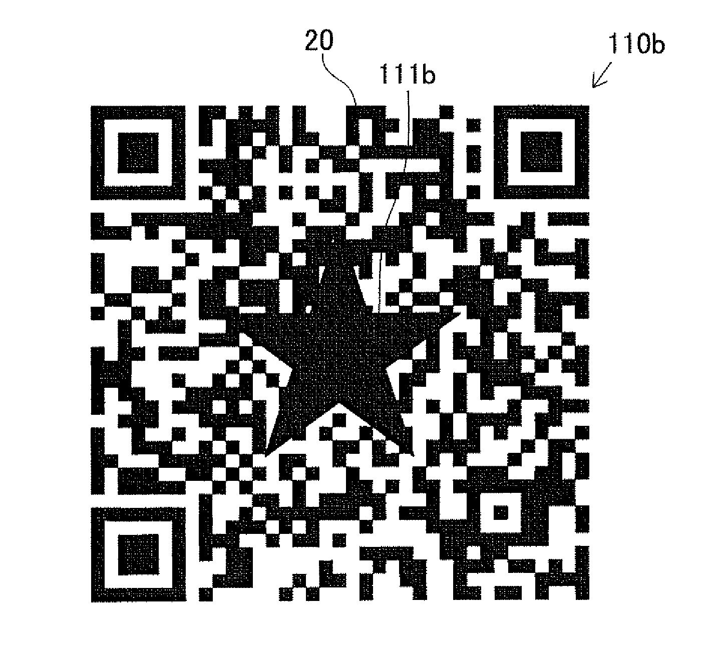
[0096]FIG. 5A is an explanatory diagram illustrating an example of an information code 10b having a covering 12, according to the second embodiment. FIG. 5B is an explanatory diagram illustrating a state where the covering 12 has been removed from the information code 10b. FIG. 6 is a flow diagram illustrating an authenticity determination process executed by the control unit 41 in the second embodiment. In FIGS. 5A and 5B, dark-color modules in the same dark color as that of the covering 12 are shown in a color lighter than that of the covering 12, i.e. shown in a gray color, for the sake...
third embodiment
[0109]With reference to FIGS. 7A, 7B and 8, hereinafter is described a third embodiment in which the information code and the information reading apparatus of the present invention are implemented.
[0110]FIG. 7A is an explanatory diagram illustrating an example of an information code 10c having coverings 13a, 13b and 13c, according to the third embodiment. FIG. 7B is an explanatory diagram illustrating a state where the coverings 13a, 13b and 13c have been removed from the information code 10c. FIG. 8 is a flow diagram illustrating an authenticity determination process performed by the control unit 41, according to the third embodiment. In FIGS. 7A and 7B, dark-color modules in the same dark color as that of the coverings 13a, 13b and 13c are shown in a color lighter than that of the coverings 13a, 13b and 13c, i.e. shown in a gray color, for the sake of descriptive convenience.
[0111]The information code 10c of the third embodiment is different from the information code of the second...
PUM
 Abstract
Description
Claims
Application Information
 - R&D
- Intellectual Property
- Life Sciences
- Materials
- Tech Scout
- Unparalleled Data Quality
- Higher Quality Content
- 60% Fewer Hallucinations
Browse by: Latest US Patents, China's latest patents, Technical Efficacy Thesaurus, Application Domain, Technology Topic, Popular Technical Reports.
© 2025 PatSnap. All rights reserved.Legal|Privacy policy|Modern Slavery Act Transparency Statement|Sitemap|About US| Contact US: help@patsnap.com


