Irrigation system and method

a technology of irrigation system and irrigation schedule, applied in watering devices, horticulture, agriculture, etc., can solve the problems of overwatering in many locations, temporal changes in irrigation schedule not allowing dynamic adjustment,

Inactive Publication Date: 2015-10-27
IBM CORP
View PDF35 Cites 5 Cited by
  • Summary
  • Abstract
  • Description
  • Claims
  • Application Information

AI Technical Summary

Benefits of technology

[0004]According to one embodiment of the present invention, an irrigation system is provided and includes a main irrigation line, one or more lateral driplines, each lateral dripline being divided into zones and including a plurality of emitters at each zone and a plurality of controllable valves disposed along each of the one or more lateral driplines at zone borders. Each one of the plurality of controllable valves is actuatable to activate corresponding emitters in the associated zone in a zone by zone cycle and each one of the plurality of emitters is replaceable to vary an amount of deliverable fluid by the zone by zone cycle.
[0005]According to another embodiment, an irrigation system is provided and includes a main irrigation line, one or more lateral driplines, each lateral dripline being divided into zones and including a plurality of emitters at each zone and a plurality of controllable valves disposed along each of the one or more lateral driplines at zone borders. Each one of the plurality of controllable valves is actuatable to activate corresponding emitters in the associated zone in a zone by zone cycle. Each one of the plurality of emitters at each zone is replaceable by another emitter with a different emission rate such that a variable amount of water can be delivered to by the zone by zone cycle.
[0006]According to yet another embodiment, a method of operating an irrigation system is provided. The method includes coupling one or more lateral driplines to a main irrigation line, dividing each lateral dripline into zones and providing each lateral dripline with a plurality of replaceable emitters at each zone, disposing a plurality of controllable valves along each of the one or more lateral driplines at zone borders and actuating each one of the plurality of controllable valves to thereby activate corresponding emitters in the associated zone.

Problems solved by technology

This can present problems, however, because industry frequently demands that drip irrigation systems be able to dynamically adjust the amount of water that is delivered to a specific location based on real time information (satellite imagery, field deployed soil moisture sensor, thermal imagery) of the water absorbed / transpired by canopy and water evaporation from soil or soil water rentention properties.
The inherent differences in soil properties and crop characteristics can thus lead to overwatering in many locations based on such uniform water delivery.
Potentially, different rate emitters can be installed in different locations but temporal changes in the irrigation schedule does not permit dynamic adjustments over time.

Method used


Image

  • Irrigation system and method
  • Irrigation system and method
  • Irrigation system and method

Examples


Embodiment Construction

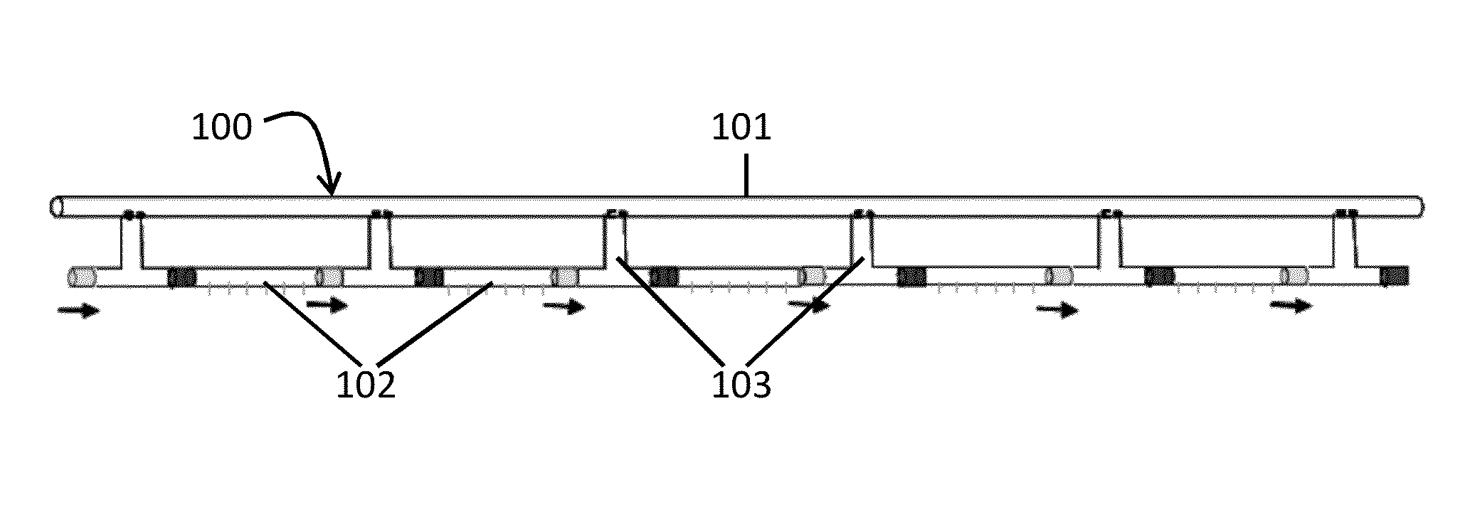
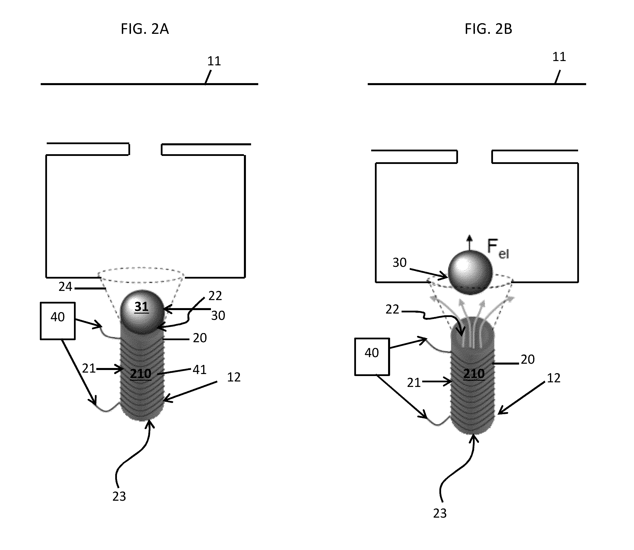
[0021]A controllable emitter is provided. The controllable emitter can be deployed in, for example, a drip irrigation system and allows a variable of amount of water to be delivered to a specific location of the drip irrigation system over a period of time. The controllable emitter includes a solenoid coil slid over a tubular element that drips the water. The upper part of the tubular element is normally blocked by a magnetic stopper in the shape of a sphere or a cone. When a current is applied to the solenoid coil, the solenoid coil creates a magnetic field that forces the magnetic stopper to move out of the blocking position and thereby allows water to flow through the tube. The current applied to the solenoid coil can be direct current (DC), such that the magnetic stopper may be displaced continuously, or alternating current (AC), such that the magnetic stopper may be displaced periodically. The solenoid coil may be electrically coupled to an electronic circuit that contains a mi...


PUM


Abstract

An irrigation system is provided and includes a main irrigation line, one or more lateral driplines, each lateral dripline being divided into zones and including a plurality of emitters at each zone and a plurality of controllable valves disposed along each of the one or more lateral driplines at zone borders. Each one of the plurality of controllable valves is actuatable to activate corresponding emitters in the associated zone in a zone by zone cycle and each one of the plurality of emitters is replaceable to vary an amount of deliverable fluid by the zone by zone cycle.

Description

BACKGROUND[0001]The present invention relates to an irrigation system and method and, more specifically, to an irrigation system and method in which lateral driplines are divided into zones with a plurality of emitters that are activated in a zone by zone cycle.[0002]Current drip irrigation systems are often equipped with pressure compensated emitters that can deliver a certain amount of water to nearby areas based on the fabrication characteristics of the emitters. Typically, the emitters will have a watering rate of 0.5, 1 or 2 gallons per hour delivery. The amount is set in the fabrication process or they can be set manually in the field. This can present problems, however, because industry frequently demands that drip irrigation systems be able to dynamically adjust the amount of water that is delivered to a specific location based on real time information (satellite imagery, field deployed soil moisture sensor, thermal imagery) of the water absorbed / transpired by canopy and wat...

Claims


Application Information

Patent Timeline
Patent Type & Authority Patents(United States)
IPC IPC(8): A62C37/20A01G25/02A01G25/16B05B12/04
CPCA01G25/02A01G25/16A01G25/162B05B12/04
Inventor HAMANN, HENDRIK F.KLEIN, LEVENTE L.RODRIGUEZ, SERGIO A. BERMUDEZSCHAPPERT, MICHAEL A.
Owner IBM CORP
Why Eureka
Try Eureka