Uterine clamp for treating postpartum hemorrhage and facilitating uterine repairs

Active Publication Date: 2015-10-27
DUCORET LLC
View PDF37 Cites 5 Cited by
  • Summary
  • Abstract
  • Description
  • Claims
  • Application Information

AI Technical Summary

Benefits of technology

The present invention provides a uterine clamp that can be easily maneuvered to capture and hold a uterus. The clamp includes an actuating handle with a ratcheted lock mechanism for securely holding the clamp in place on the uterus. This allows the surgeon to maintain compression on the uterus and safely release it for further manipulation during the postpartum phase of delivery. The use of the clamp eliminates the emergency situation and increases the likelihood of successful procedures for achieving permanent hemostasis.

Problems solved by technology

Accordingly, when the uterus sheds the placenta post-delivery there is a potential for severe and rapid hemorrhaging.
If PPH occurs the mother can lose massive amounts of blood in a very short time, and hemorrhaging due to conditions such as atony is a leading cause of death incident to childbirth.
This can cause portions of the placenta to remain attached to the uterine wall instead of being shed in the normal fashion, which can result in excessive bleeding at the site of the placental invasion into the uterine wall.
While drug therapy is widely used in first-world countries, the required drugs are often not available in less developed areas of the world.
Although this technique is generally effective in achieving hemostasis of a hemorrhaging uterus, its complexity can potentially be a serious shortcoming.
During PPH, the patient's abdominal cavity rapidly fills with blood and her vital signs weaken at a rate that even experienced physicians can find alarming and stress-producing.
As for B-Lynch procedures, they can take vital seconds to implement, and surgeons, particularly those with insufficient experience in using these procedures, may not be able to achieve hemostasis in time to save the patient or preclude more radical interventions such as hysterectomy.
Although certain modifications intended to simplify the classic B-lynch technique are described in the literature, see Hayman, R. G., et al., “Uterine Compression Sutures: Surgical Management of Postpartum Hemorrhage,” cited above, they still may be too complicated for an inexperienced surgeon to implement in time to save the patient or preempt a hysterectomy.
However, the hemorrhage site can also be at a location lower in the fundus of the uterus, in which case suturing at locations such as those shown in FIG. 4 will be ineffective and cause time to be lost before the sutures are applied to the correct location.
This means that these devices will be costly and also inherently involve a certain amount of complexity in their operation.
Although clinically effective inflatable devices that compress the uterine walls from the inside are known in the art, their cost and the necessity for auxiliary operating / control apparatus may make them unattractive or unavailable in less developed countries.
For one, it would seem to be unwieldy to maneuver into place, thus costing precious seconds during emergency hemorrhaging.
It also has many parts and would likely prove expensive to manufacture, making it less attractive for use in third world countries where the need is the greatest for an inexpensive way of managing PPH.
It also uses an elastic belt made of rubber or like material, which would present sterilization issues.
No reports of clinical experience with this device have been found, but as with the '925 patent clamp, it may also prove to be too unwieldy to provide effective emergency intervention in the presence of PPH.
Not only is the handle and cantilevered plate configuration bulky, but the orientation of the plates relative to each other is fixed, thus forcing the surgeon to manipulate the entire clamp assembly into the proper orientation so that the plates are positioned to compress opposing walls of the uterus.
Accordingly, there is unknown in the art a device that can be rapidly and properly positioned on the uterus to achieve immediate hemostasis in the presence of PPH, while being simple in design and inexpensive to manufacture to allow for widespread use in underdeveloped countries in which uterotonic drugs are often unavailable.
Another postpartum issue often faced by the delivering physician is the need to move the postpartum uterus after a C-section to permit repair of uterine trauma resulting from the procedure.
For example, a C-section inherently involves an incision IN (see FIGS. 1-3) at the lower uterine segment, and repairing this incision can present challenges to the surgeon because it sometimes requires elevating the exteriorized uterus from the patient's abdomen to minimize possible damage to surrounding organs while performing the necessary repairs.
However, this may prove awkward in certain situations and for some patients.
For example, it can often be difficult to reach and maneuver the uterus of an obese patient into a favorable position to perform a desired postpartum procedure.

Method used


Image

  • Uterine clamp for treating postpartum hemorrhage and facilitating uterine repairs
  • Uterine clamp for treating postpartum hemorrhage and facilitating uterine repairs
  • Uterine clamp for treating postpartum hemorrhage and facilitating uterine repairs

Examples


second embodiment

II. SECOND EMBODIMENT HAVING ENHANCED CLAMPING CAPABILITIES

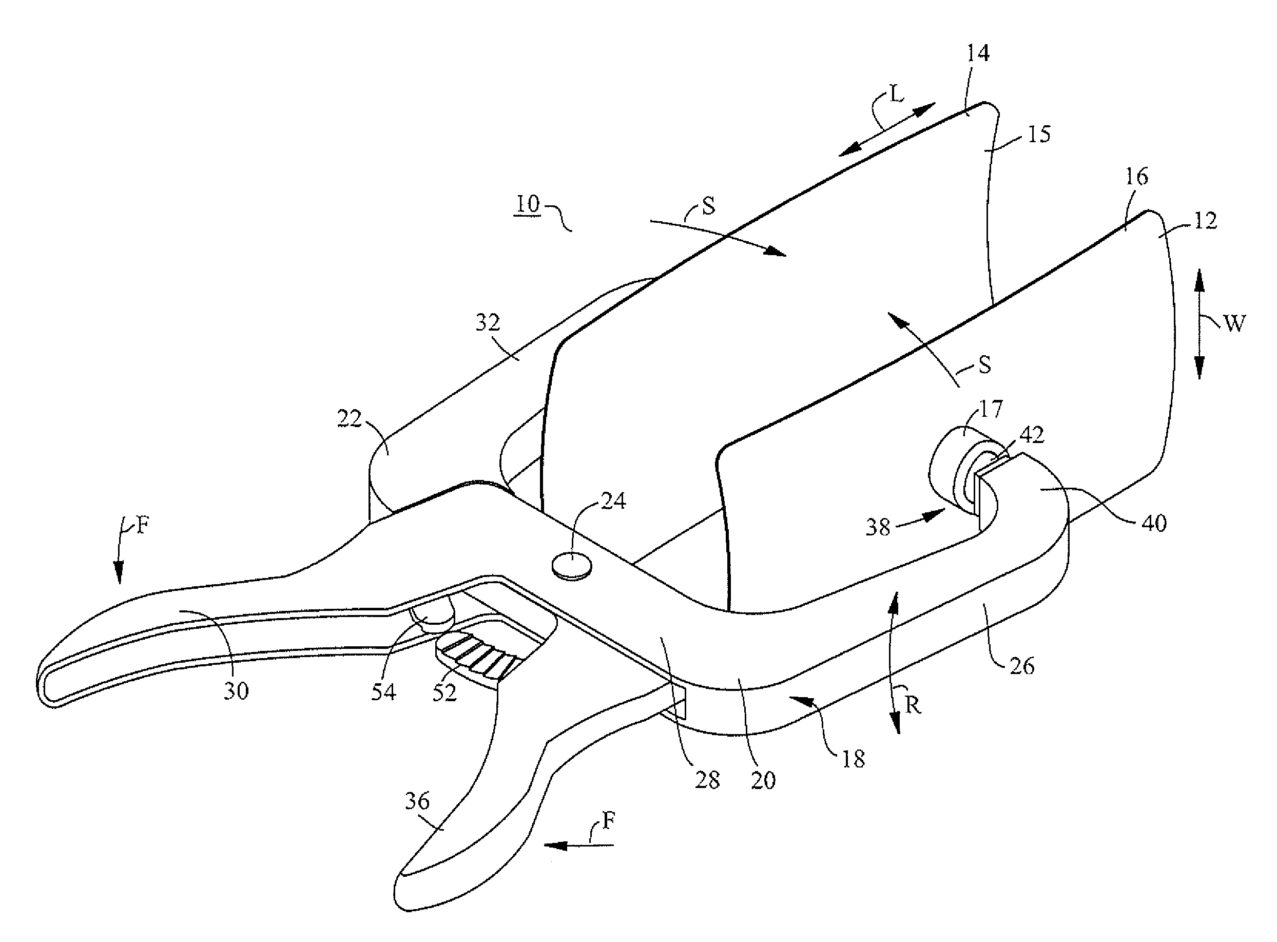
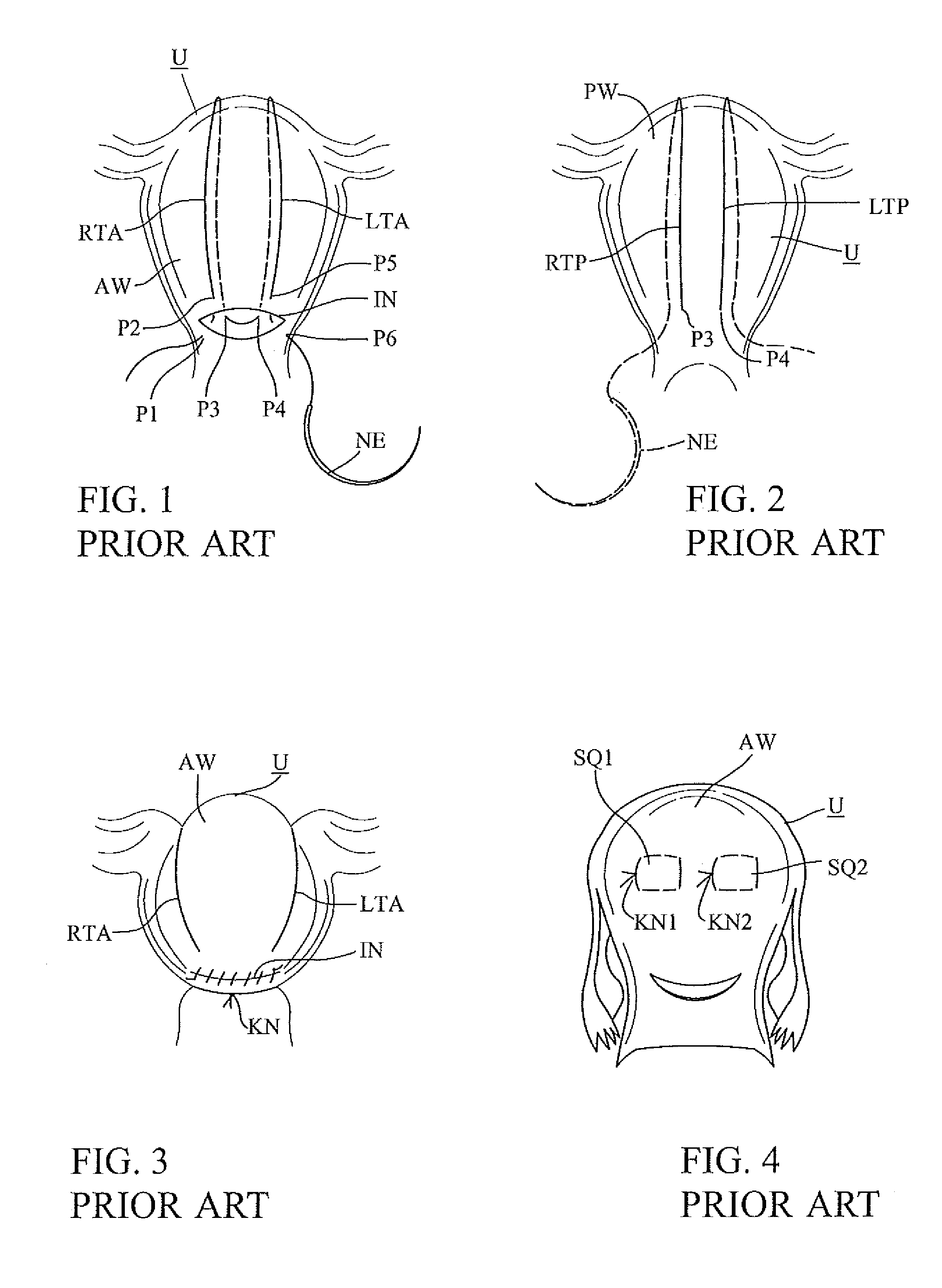
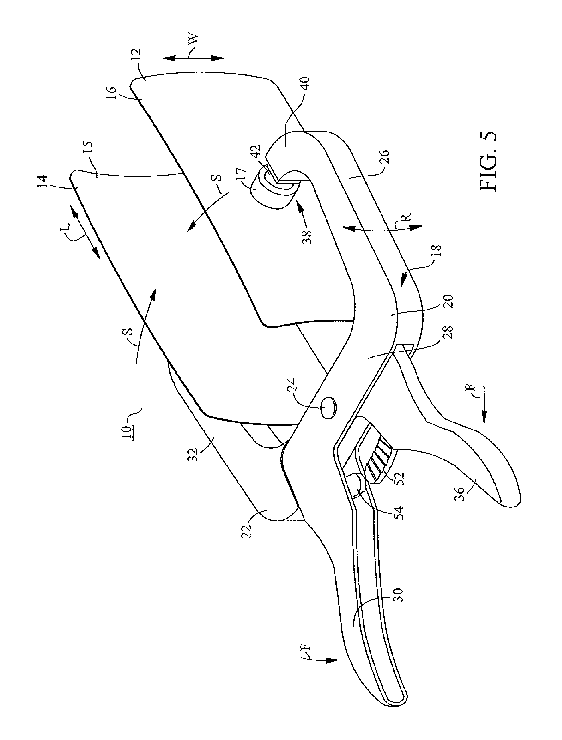
[0046]A clamp in accordance with the present invention can also include additional features for enhancing its capabilities for facilitating routine postpartum uterine repairs and for other known PPH treatment interventions, such as a B-Lynch procedure, that require access to the posterior uterine wall to implement. FIGS. 6 and 7 illustrate an alternate embodiment of a clamp particularly adapted for that purpose. FIGS. 6 and 7 use the same reference numerals as the previous embodiments for similar features, except that they have a “1” preceding them. In other words, a clamp 110 in FIGS. 6 and 7 represents a second embodiment of the clamp 10 depicted and described above, with the same features, except where explicitly stated otherwise or as will be apparent as the description proceeds. As used herein, “B-Lynch procedure” means the procedure described in connection with FIGS. 1 to 3 above or variations thereof described in the ...

third embodiment

III. THIRD EMBODIMENT PERMITTING USE OF SQUARE SUTURING TECHNIQUES

[0049]A uterine clamp according to the principles described herein can be used in conjunction with other known PPH interventions to mitigate the emergency conditions under which such interventions heretofore have taken place. The embodiment of FIG. 6, discussed above, makes it possible to perform the more permanent B-Lynch procedure under more controlled conditions rather than as part of an emergency response. That is, while a clamp as described and claimed herein may in itself promote permanent hemostasis, it has the added advantage of permitting the employment of more permanent interventions while remaining in place. For example, a clamp in accordance with the present invention can also be adapted to permit the use of procedures in which the major uterine walls are sutured together, such as the square suturing techniques described above in conjunction with FIG. 4. FIGS. 8 and 9 illustrate a third embodiment of a cla...


PUM


Abstract

A medical clamp for holding a uterus includes a first and second curved plates that capture between them the major exterior walls of the uterus, and an operating handle having pivotally connected first and second actuating arms, each of which has a distal portion and a proximal portion with a grip for a user, whereby the distal portions are moved toward each other when the user moves the grips toward each other to capture the uterus between the plates. Ball-and-socket joints connect the distal handle portions of the actuating arms to respective plates. The ball-and socket joints enable rapid positioning of the clamp on the uterus to arrest emergency postpartum hemorrhaging, assist in exerting pressure on the uterus over the entire extent of the plates, facilitate manipulation of the uterus using the clamp, and permit other surgical interventions to be performed with the clamp in place.

Description

BACKGROUND OF THE INVENTION[0001]1. Field of the Invention[0002]The present invention relates to a device for clamping a uterus, and more particularly, to a medical clamp for compressing a uterus to achieve immediate cessation of blood loss from postpartum hemorrhage and provide sufficient time for other interventions that can promote permanent hemostasis and / or for securely grasping a uterus to permit a surgeon to readily position it to facilitate postpartum repairs such as suturing a caesarean incision.[0003]2. Description of Related Art[0004]During pregnancy the placenta implants itself into the internal wall of the uterus and is naturally expelled after delivery. The placenta is rich in blood vessels intimately interconnected with blood vessels in the uterine wall. Accordingly, when the uterus sheds the placenta post-delivery there is a potential for severe and rapid hemorrhaging. In normal childbirth the uterine walls, which are heavily muscled, firmly contract upon themselves ...

Claims


Application Information

Patent Timeline
IPC IPC(8): A61B17/42A61B17/46A61B17/122A61B17/44A61B17/12
CPCA61B17/44A61B17/42A61B17/122A61B2017/4216A61B2017/12004A61B17/2812A61B17/4241
Inventor DIBENEDETTO, ROBERT J.
Owner DUCORET LLC
Why Eureka
Try Eureka