
Bidirectional fast fourier transform in an integrated circuit device

a fourier transform and integrated circuit technology, applied in the field of bidirectional fast fourier transform (fft) architectures in integrated circuit devices, can solve the problems of low throughput, high usage of logic and memory resources, and general cost and inefficiency of fft and ifft algorithms on data, and achieve the effect of optimizing delay memory usag

Active Publication Date: 2015-10-27
ALTERA CORP
View PDF4 Cites 7 Cited by
  • Summary
  • Abstract
  • Description
  • Claims
  • Application Information

AI Technical Summary

Benefits of technology

The patent describes a way to create a device that can perform Fast Fourier Transform (FFT) operations in both directions. This allows for more flexible and efficient processing of data. The device uses a streaming FFT architecture and can handle natural and reversed order input. It also allows for optimal memory usage when performing mixed-radix operations. A method for using the device is also provided, along with a way to configure it on a programmable device. The technical effect of this patent is to provide a more efficient and flexible device for FFT operations.

Problems solved by technology

Because it is generally expensive and inefficient to perform FFT and IFFT algorithms on data ordered in natural order, existing applications either reorder the data in radix-reverse order or use decimation-in-time (DIT) algorithms.
These solutions suffer from low throughput and high usage of logic and memory resources.
These solutions are also incapable of computing certain radix values, such as radix-2 FFT or mixed radix 4 / 2 FFT.
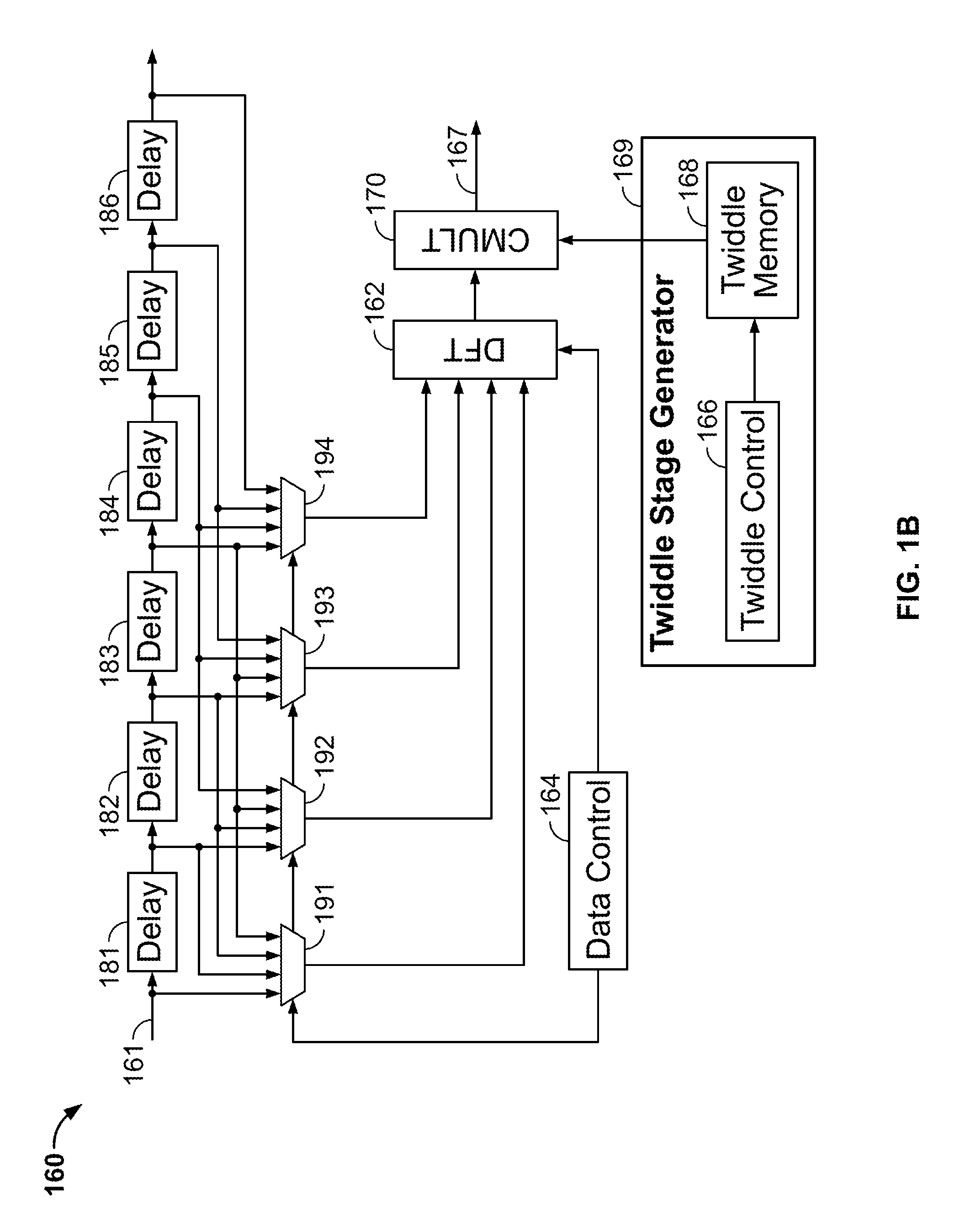
The serial architecture of FIG. 2 has many limitations.
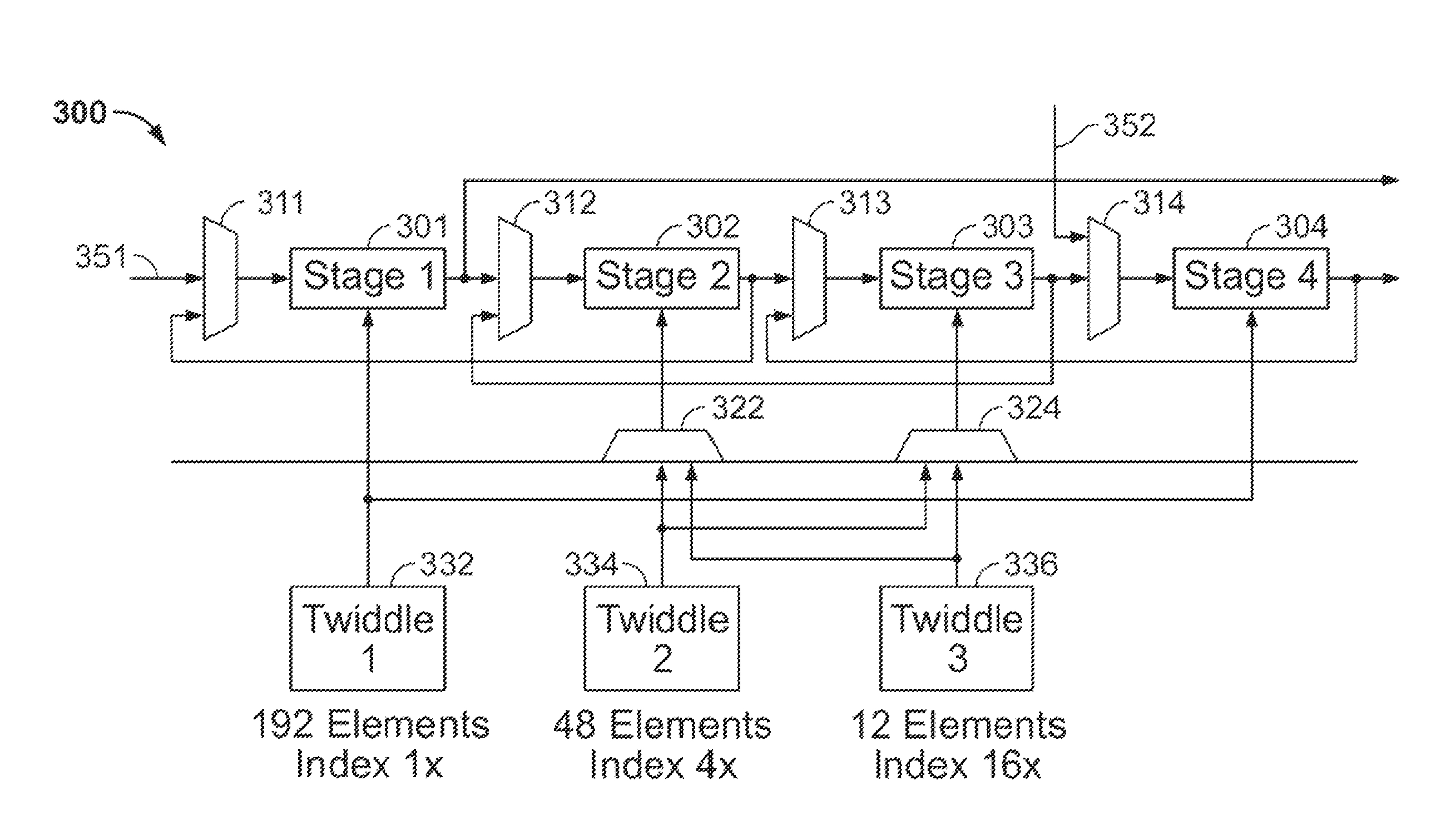
First, the serial architecture of FIG. 2 is unidirectional, and can only perform FFT operations on data input from left to right.
Second, the serial architecture of FIG. 2 can implement FFT operations in only one direction—it can either perform forward (FFT) operations or reverse (IFFT) operations, but not both.
Third, each stage in the serial architecture of FIG. 2 is limited to the configuration of its associated twiddle stage generator, and as such can function only in one specific FFT pass in only one direction of the implemented FFT operation.
This has several disadvantages, such as lower performance, increased usage, and lower throughput.

Method used


Image

  • Bidirectional fast fourier transform in an integrated circuit device
  • Bidirectional fast fourier transform in an integrated circuit device
  • Bidirectional fast fourier transform in an integrated circuit device

Examples


Embodiment Construction

[0025]To provide an overall understanding of the invention, certain illustrative embodiments will now be described. However, it will be understood by one of ordinary skill in the art that the systems and methods described herein may be adapted and modified as is appropriate for the application being addressed and that the systems and methods described herein may be employed in other suitable applications, and that such other additions and modifications will not depart from the scope hereof.

[0026]Unlike the unidirectional architecture of FIG. 2, embodiments of the present disclosure may allow bidirectional processing of FFT operations and may perform both reverse and forward FFT operations using the same structure. This may substantially improve performance, lower usage, and decrease size. Details of how to operationalize FFT bidirectionality are further described below.

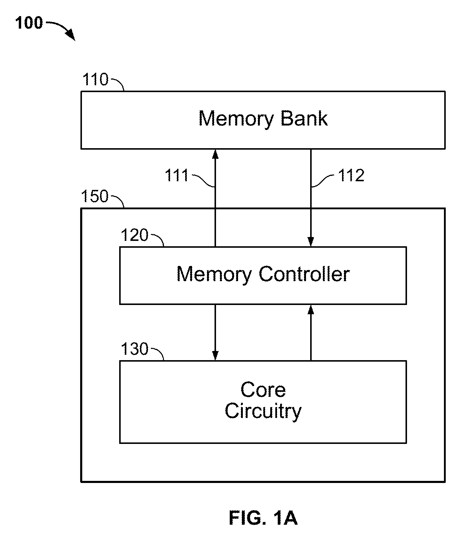
[0027]FIG. 1A is a simplified block diagram of an illustrative embodiment of an FFT computation architecture where ...


PUM


Abstract

Methods and systems for performing Fast Fourier Transform (FFT) operations are disclosed. A plurality of cascaded stages compute a selectable one of a forward decimation-in-frequency (DFT) FFT operation in a forward direction from an ith stage to a jth stage, and a reverse DFT FFT operation in a reverse direction from the jth stage to the ith stage. The reduction in time and resource usage from employing the disclosed bidirectional DIF FFT architectures may significantly increase performance of DIF applications, for example, ones that involve streaming FFTs.

Description

CROSS-REFERENCE TO RELATED APPLICATIONS[0001]This application claims the benefit under 35 U.S.C. §119(e) of U.S. Provisional Application No. 61 / 747,793, filed Dec. 31, 2012, which is hereby incorporated by reference herein in its entirety.FIELD OF THE INVENTION[0002]This disclosure relates to providing Fast Fourier Transform (FFT) architectures in an integrated circuit device, for example, an application-specific standard product (ASSP), an application-specific integrated circuit (ASIC), a programmable logic device (PLD), a field programmable gate array (FPGA), a full-custom chip, or a dedicated chip.BACKGROUND OF THE INVENTION[0003]An FFT calculation includes reading an input data sequence in the form of time-domain samples x[n], n=0, . . . , N−1, where N is the length of the input data sequence, and outputting an FFT data sequence in the form of frequency-domain components X[k], k=0, . . . , N−1. Such a calculation is conventionally called an N-point FFT. Some FFT algorithms use a...

Claims


Application Information

Patent Timeline
Patent Type & Authority Patents(United States)
IPC IPC(8): G06F17/14
CPCG06F17/142
Inventor LANGHAMMER, MARTIN
Owner ALTERA CORP
Learn More