
Visual aid generating system, device, and method

a visual aid and generating system technology, applied in the field of image display systems, can solve the problem that the system cannot be used for any operational credit, and achieve the effect of enhancing vision, increasing situational awareness, and increasing pilots' ability to recognize the runway environmen

Active Publication Date: 2015-11-03
ROCKWELL COLLINS INC
View PDF6 Cites 53 Cited by
  • Summary
  • Abstract
  • Description
  • Claims
  • Application Information

AI Technical Summary

Benefits of technology

The patent describes a system and method for combining image data to provide a visual cue to a pilot to help them recognize the location where lighting systems are being used on a runway. This system helps to increase the pilot's situational awareness and enhance their ability to recognize the runway environment.

Problems solved by technology

While certainly enhancing the flight crew's awareness of where they are in space, and where they are relative to terrain, obstacles and the airport, the system cannot currently be used for any operational credit.

Method used


Image

  • Visual aid generating system, device, and method
  • Visual aid generating system, device, and method
  • Visual aid generating system, device, and method

Examples


Embodiment Construction

[0030]In the following description, several specific details are presented to provide a thorough understanding of embodiments of the invention. One skilled in the relevant art will recognize, however, that the invention can be practiced without one or more of the specific details, or in combination with other components, etc. In other instances, well-known implementations or operations are not shown or described in detail to avoid obscuring aspects of various embodiments of the invention.

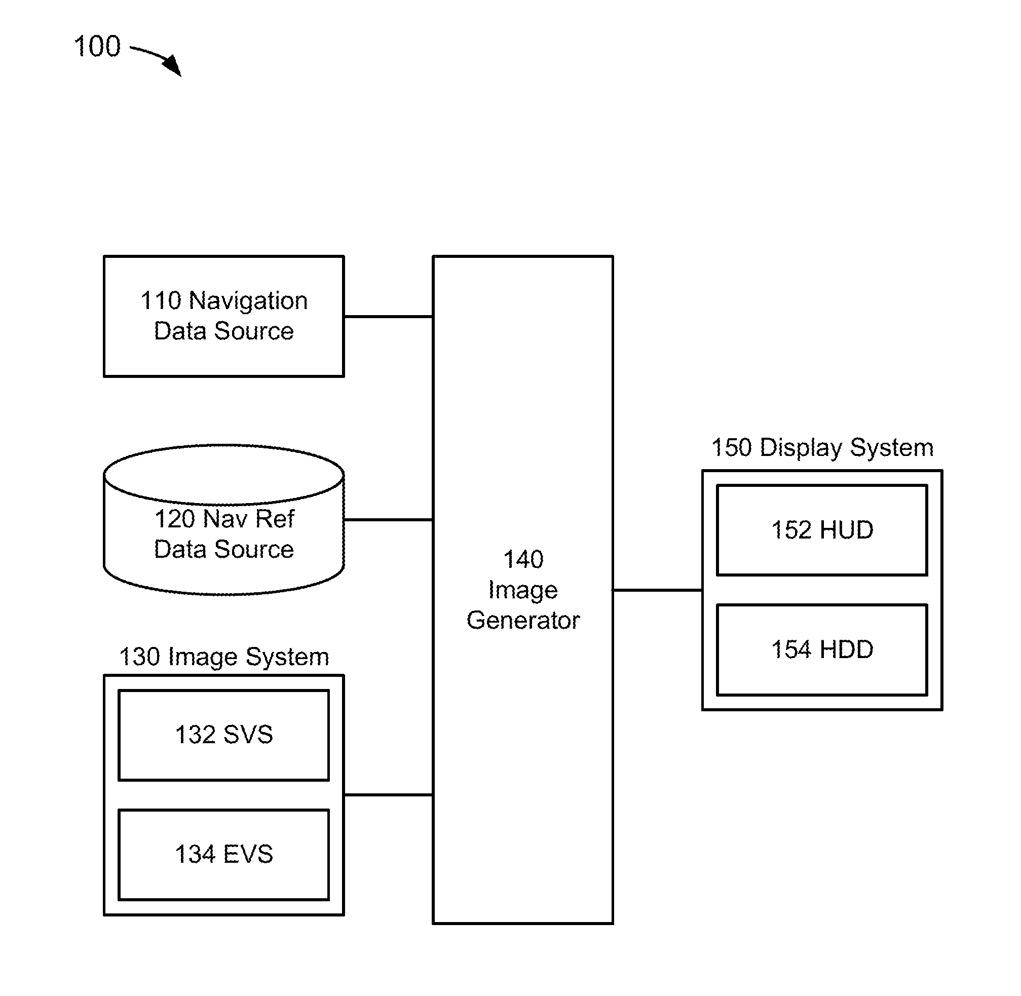
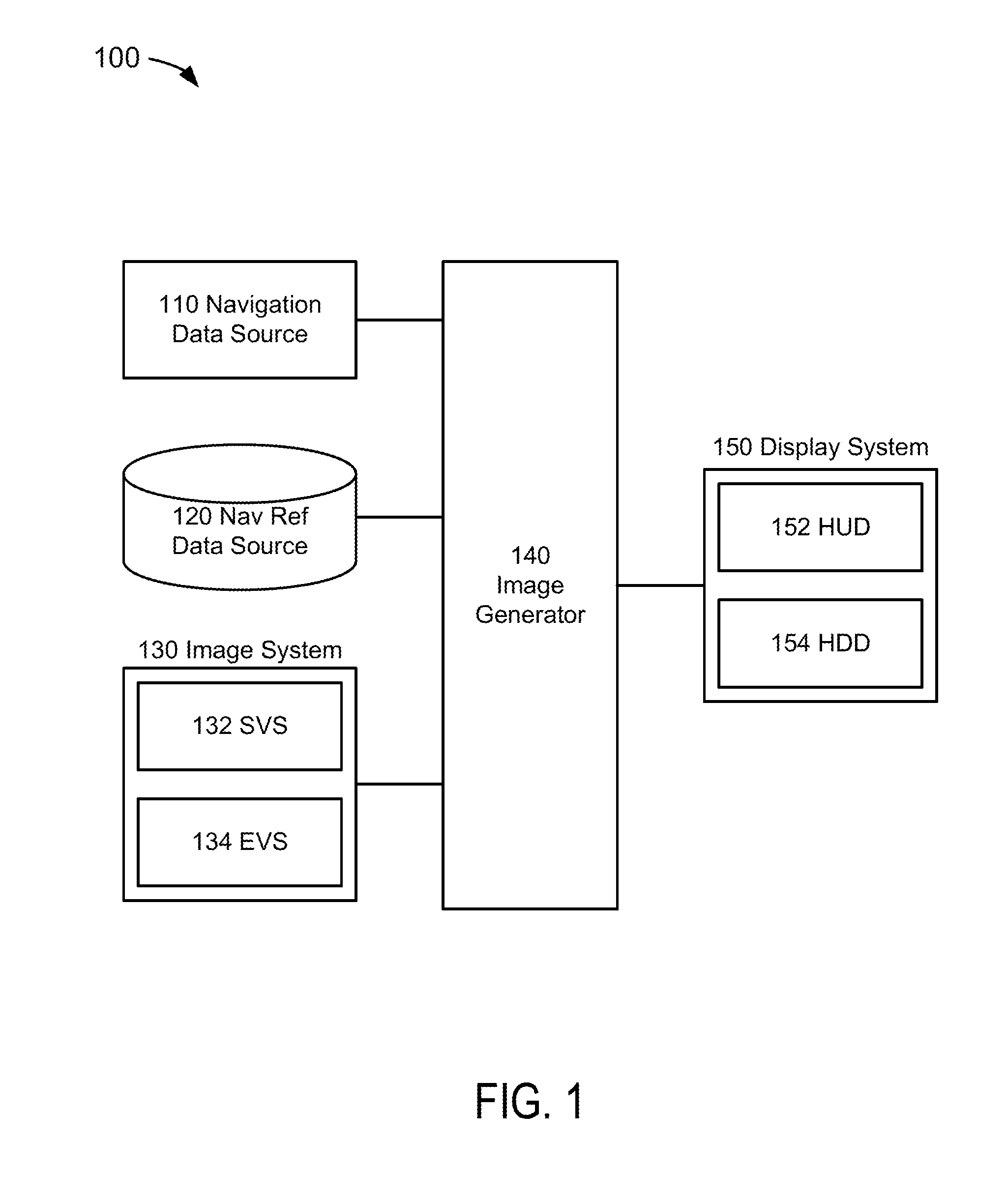
[0031]FIG. 1 depicts a functional block diagram of a visual aid data generating system 100 suitable for implementation of the techniques described herein. The functional blocks of the system may include a navigation data source 110, a navigation reference data source 120, an image system 130, an image generator (“IG”) 140, and a display system 150.

[0032]In an embodiment of FIG. 1, the navigation data source 110 could be comprised of a system or systems that provide navigation data information in an ...


PUM


Abstract

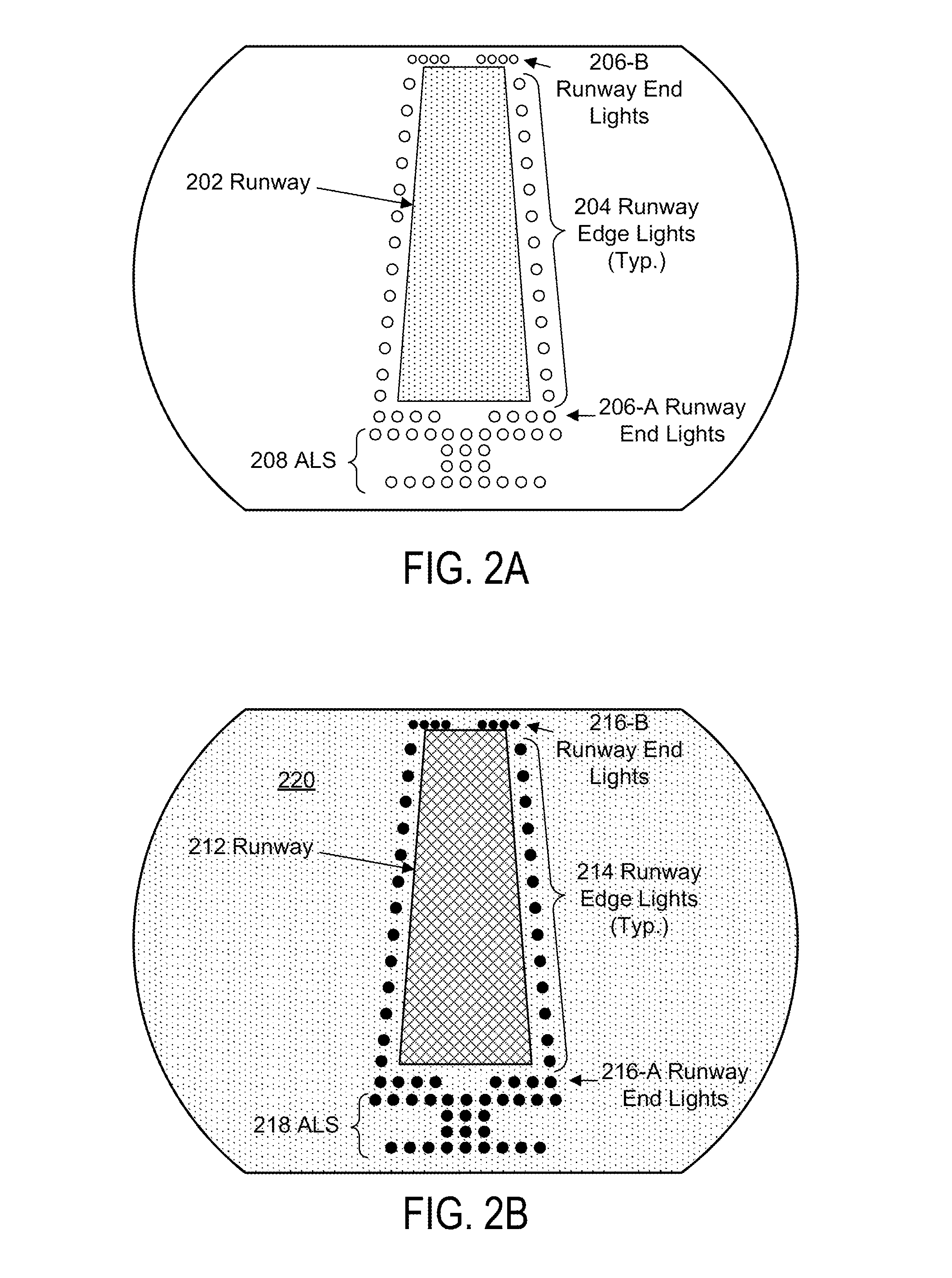
Present novel and non-trivial system, device and method for generating visual aid image data are disclosed. In one embodiment, an image generator receives navigation data representative of at least one surface of interest (e.g., runway of intended landing) and aircraft position; retrieves navigation reference data representative of surface information; creates zone data representative of a lighting awareness zone for each surface of interest; receives first image data from a first source; and generates second image data as a function of the first image data and the zone data, thereby generating a visual aid to increase situational awareness of a pilot by enhancing his or her ability to detect or recognize the runway environment as presented by an enhanced image. In an additional embodiment, the image generator receives and includes third image data in the function for generating the second data.

Description

BACKGROUND OF THE INVENTION[0001]1. Field of the Invention[0002]This invention pertains generally to the field of image display systems such as, but not limited to, aircraft display systems.[0003]2. Description of the Related Art[0004]Synthetic Vision Systems (singularly, “SVS”) have been operating for a few years now in a wide range of aircraft; from small, General Aviation airplanes, right up to long range corporate jets; however, these systems are approved or certified for situational awareness only, with the aim of increasing flight safety by providing the flight crew with a real-time, intuitive representation of the external environment. The synthetic scene is rendered from the pilot's eye viewpoint, and typically contains the following: terrain, obstacles, rivers and lakes, and the environment of airports. While certainly enhancing the flight crew's awareness of where they are in space, and where they are relative to terrain, obstacles and the airport, the system cannot curren...

Claims


Application Information

Patent Timeline
Patent Type & Authority Patents(United States)
IPC IPC(8): G05D1/00G05D1/10G01C23/00B64D45/04
CPCB64D45/04G01C23/00
Inventor BELL, DOUGLAS A.BARBER, SARAH
Owner ROCKWELL COLLINS INC
Learn More