Reusable module for launcher

a technology for reusable modules and launchers, applied in the field of reusable modules for launchers, can solve the problems of high development cost, low first stage, and long development cycle of launchers

Active Publication Date: 2015-11-03
ARIANEGRP SAS
View PDF21 Cites 5 Cited by
  • Summary
  • Abstract
  • Description
  • Claims
  • Application Information

AI Technical Summary

Benefits of technology

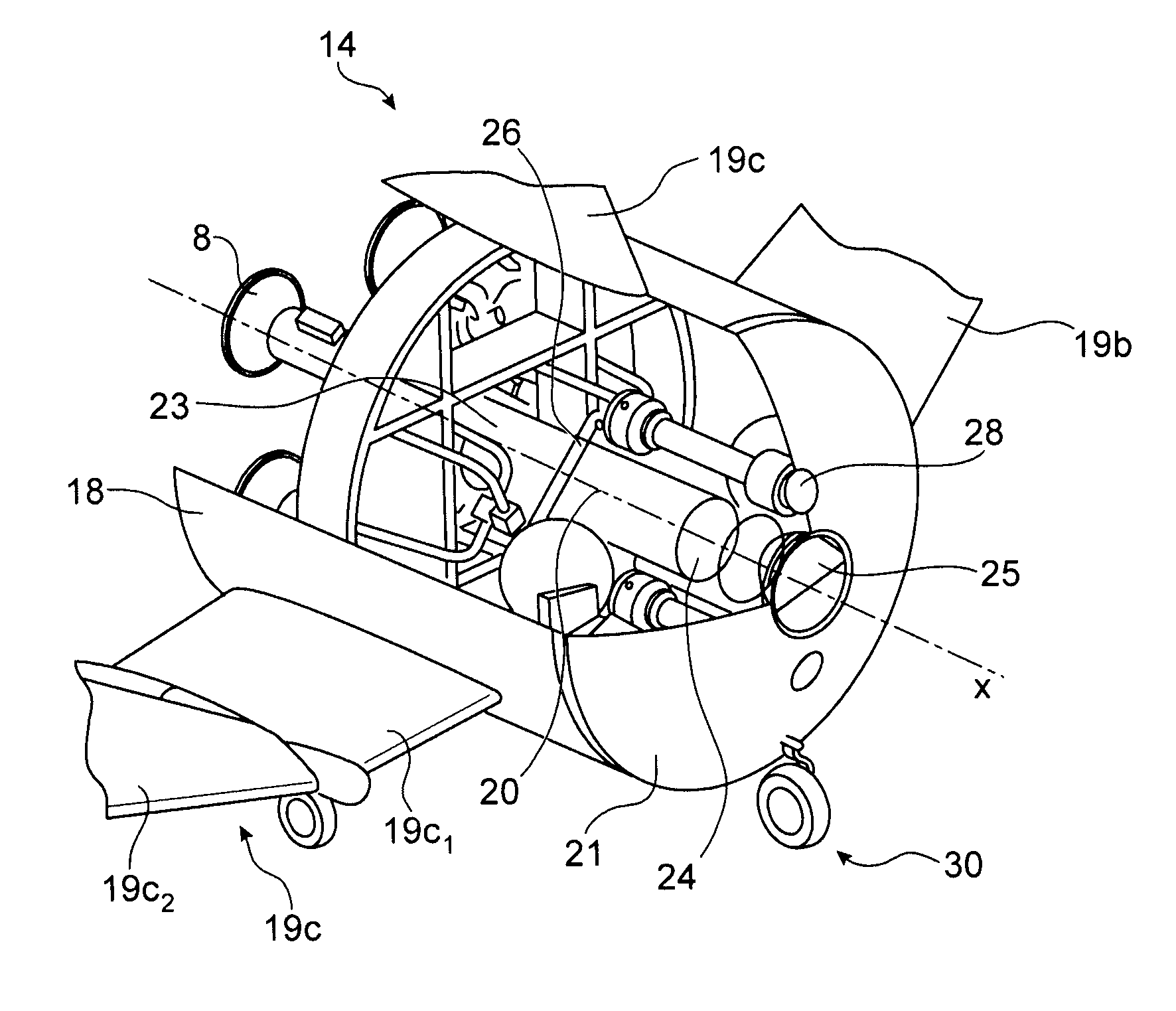
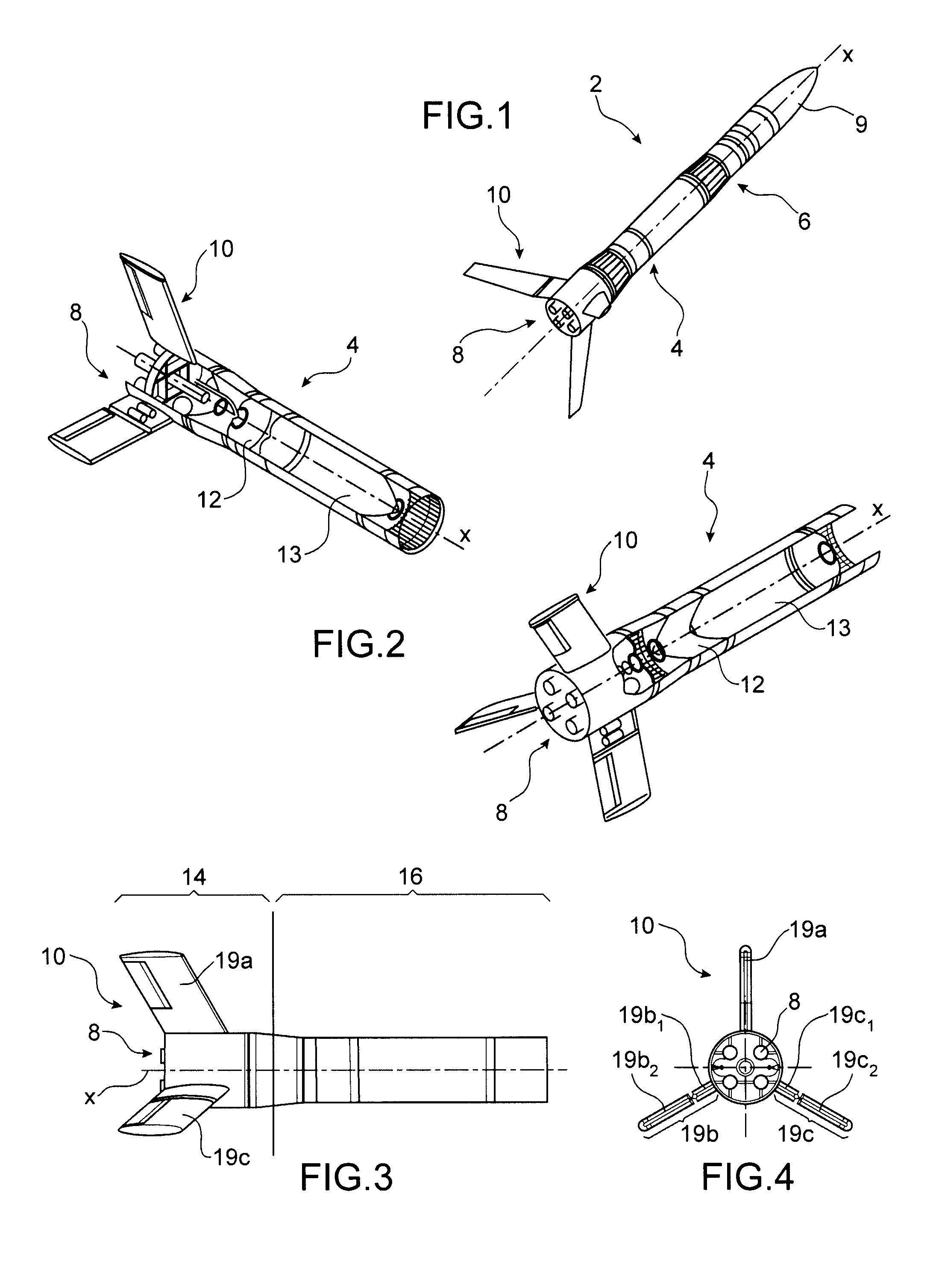
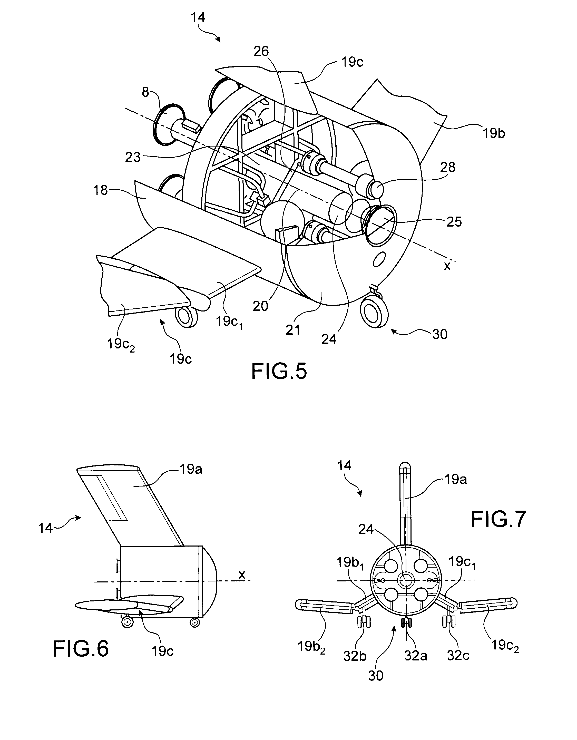
[0011]In other words, the aim is to reuse the elements having a high cost; to this end a detachable module with a airfoil and an aircraft engine allowing it to be landed on a conventional runway are manufactured. Non-recovery of the tanks enables the recovered part to be made much more easily recoverable, due to its increased density.
[0012]The lower position of the recovered part associated with the presence of tail units also gives the launcher itself greater stability during the ascending phase.
[0013]Advantageously, part of the launcher's tail unit is designed to be used as a wing surface for the return to earth, thereby eliminating the problem of the attachment of the wings, whilst not increasing the mass of the launcher.
[0019]Advantageously, the recoverable module has a blunt nose, to increase the supersonic wave drag during the initial phase of atmospheric re-entry, and to contribute to the deceleration of the recoverable module.

Problems solved by technology

The development and manufacture of a launcher represents a very substantial cost.
Furthermore, such development is very lengthy.
However, such a construction has several disadvantages.
Firstly, at the time of separation from the second stage, the tanks of the intermediate part are empty; they therefore represent a very large volume of very low mass.
The average density of the first stage is consequently low, making the first stage very difficult to recover.
The addition of this wing surface and of strengtheners represents an additional mass which must be propelled, therefore implying an increase of the size of the tanks, and therefore a substantial increase of the cost of the launcher.
Consequently, the gain obtained by recovering the first stage in full is partially lost in the modifications implied to allow this recovery.
In addition, this type of launcher is very different from known launchers.

Method used


Image

  • Reusable module for launcher
  • Reusable module for launcher
  • Reusable module for launcher

Examples


Embodiment Construction

[0010]The aim described above is attained by a launcher comprising at least one stage, where the said stage is divided into two parts, a first part containing the rocket motors, the avionics, the propulsion bay, and the tank pressurisation system and the means of independent air-breathing flight (airfoil, air-breathing motor and its fuel), and a second part formed by the tanks, where both parts can be separated after launch, with the first part comprising means to allow its return to earth without damage in order to be reused in a new launcher. The first part forms the lower part of the said stage.

[0011]In other words, the aim is to reuse the elements having a high cost; to this end a detachable module with a airfoil and an aircraft engine allowing it to be landed on a conventional runway are manufactured. Non-recovery of the tanks enables the recovered part to be made much more easily recoverable, due to its increased density.

[0012]The lower position of the recovered part associate...


PUM


Abstract

A propulsion module configured to launch a craft into space including a recoverable module and a non-recovered part, which is secured to the recoverable module at launch. The recoverable module includes a propulsive system to launch the craft, systems for command and control of the propulsive system, a subsonic flight propulsion motor, airfoils for the subsonic flight, a landing gear, and a braking parachute. The recoverable module is installed in a lower position of the craft when the craft is in the launch position. The non-recovered part includes at least one tank to feed the propulsive system. The recoverable module and the non-recovered part are configured to be separated when the propulsion module reaches a given altitude, and the recoverable module is capable of landing in a controlled fashion after a coasting flight, for example for a return to the launch site.

Description

TECHNICAL FIELD AND PRIOR ART[0001]The present invention relates to a reusable model intended to form part of a propulsion module intended to send a craft into space, where the craft is, for example, a launcher intended to send a payload into space, such as telecommunication satellites.[0002]The Ariane V rocket is a well-known example of a launcher comprising a central body formed of a first stage, called the main cryogenic stage (EPC) and a second stage, called the storable propulsive stage (EPS). The first stage transports liquid oxygen and hydrogen cooled to very low temperatures, and these fluids supply a cryogenic motor. The final stage supports the payload to be launched, for example a satellite. The rocket also comprises, either side of the central body, two solid rocket booster stages (EAP) used for lift-off. The cryogenic motor is started before lift-off and operates until the separation of the first and second stages.[0003]There are also launches using methane-based propul...

Claims


Application Information

Patent Timeline
Patent Type & Authority Patents(United States)
IPC IPC(8): B64G1/00B64G1/40
CPCB64G1/002B64G1/401B64G1/402
Inventor PRAMPOLINI, MARCOGOGDET, OLIVIER
Owner ARIANEGRP SAS
Why Eureka
Try Eureka