Sputter apparatus, control device for sputter apparatus and film formation method

a control device and film technology, applied in the direction of electrolysis components, vacuum evaporation coatings, coatings, etc., to achieve the effect of favorable film thickness distribution

Active Publication Date: 2015-11-03
CANON ANELVA CORP
View PDF7 Cites 0 Cited by
  • Summary
  • Abstract
  • Description
  • Claims
  • Application Information

AI Technical Summary

Benefits of technology

[0008]In view of these problems, the present invention aims to provide a sputter apparatus, a control device for the sputter apparatus, and a film formation method that are capable of obtaining a favorable film thickness distribution in a film deposited by sputter.
[0012]According to the present invention, a favorable film thickness distribution can be obtained in a film deposited by sputter.

Problems solved by technology

In general, however, the deposition rate varies by a certain amount at the sputter starts, and requires a certain period of time is needed to stabilize the deposition rate.

Method used


Image

  • Sputter apparatus, control device for sputter apparatus and film formation method
  • Sputter apparatus, control device for sputter apparatus and film formation method
  • Sputter apparatus, control device for sputter apparatus and film formation method

Examples


first embodiment

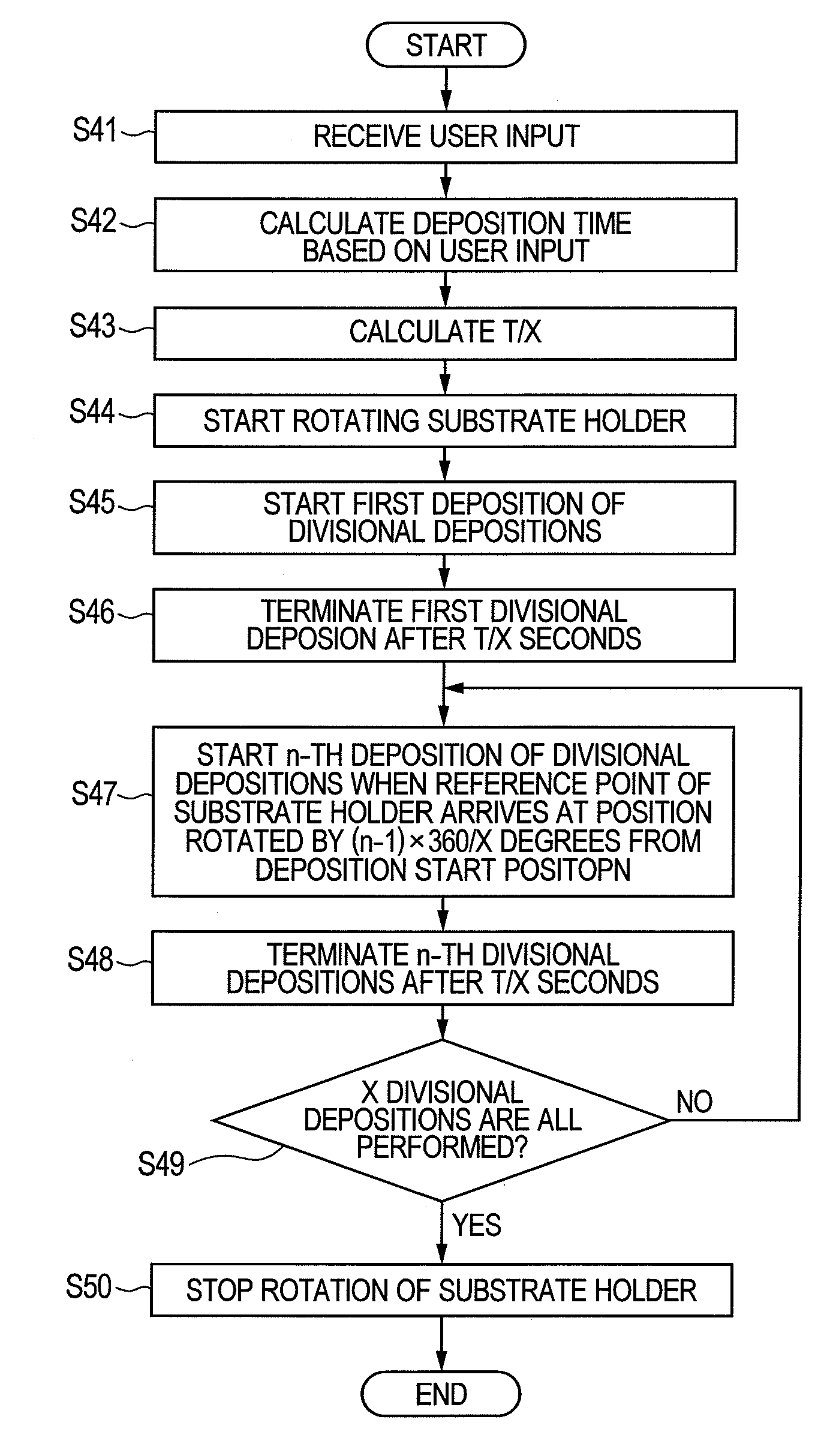
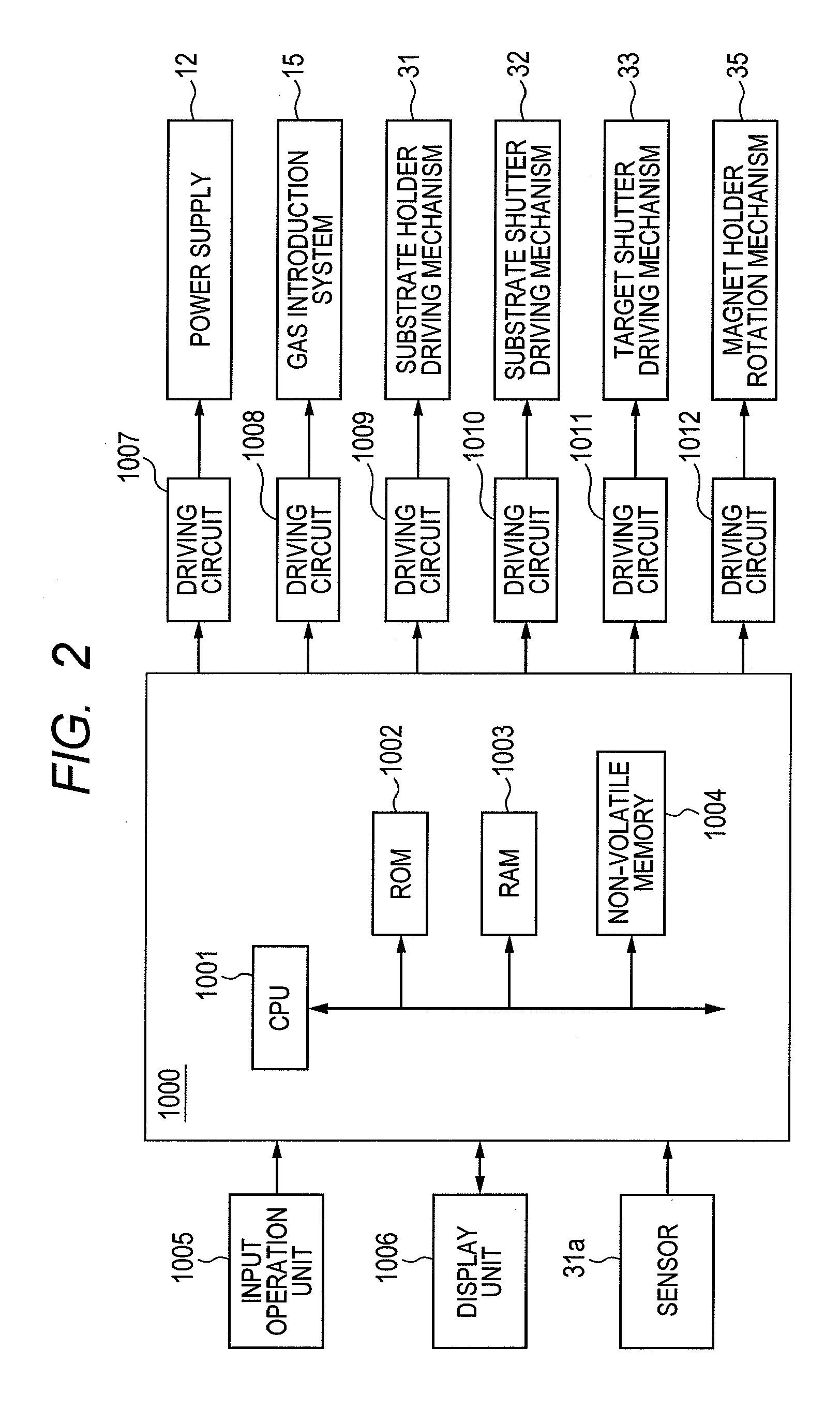
[0041]In this embodiment, the control (start and termination) of divisional depositions is carried out by controlling supply of a predetermined voltage for plasma generation from the power supply 12 as voltage supply means to the target holder 6 as a cathode. Accordingly, the control device 1000 is configured to control the power supply 12 so that the power supply 12 supplies the predetermined voltage to the target holder 6 in order that each of X divisional depositions can be performed just for T / X seconds, while causing the substrate holder 7 (substrate holding surface 7a) to rotate at the fixed rotation speed by controlling the substrate holder driving mechanism 31. More specifically, the control device 1000 is configured to cause the first divisional deposition to be performed just for T / X seconds by controlling the power supply 12 so that the power supply 12 supplies the predetermined voltage to the target holder 6 just for T / X seconds, with the setting of the rotation angle θ ...

second embodiment

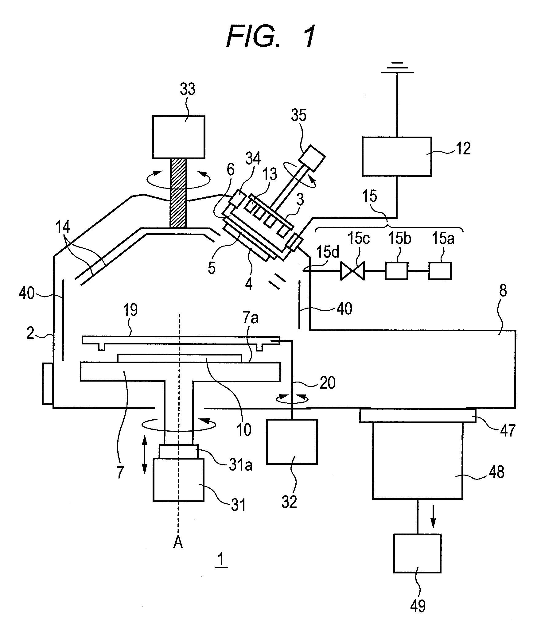
[0061]In this embodiment, the control (start and termination) of divisional depositions is carried out by controlling the open state and the close state of the target shutter 14 and / or the substrate shutter 19.

[0062]In the case of using the target shutter 14 and / or the substrate shutter 19, the deposition is controlled by exposure of the target 4 to the substrate 10 and by blockage of the exposure, while the discharge on the target 4 is continuously performed. For example, in the case of using the target shutter 14 and the substrate shutter 19, when both of the target shutter 14 and the substrate shutter 19 are switched from the close state to the open state under a condition where the plasma for sputter is generated, the target 4 is exposed to the substrate 10 and the deposition is stated. On the other hand, when both of the target shutter 14 and the substrate shutter 19 are switched from the open state to the close state in the deposition, the exposure of the target 4 to the subst...


PUM

PropertyMeasurementUnit
rotation angleaaaaaaaaaa
voltageaaaaaaaaaa
rotationaaaaaaaaaa

Abstract

In an embodiment of the present invention, the following operations are performed while a substrate holder is being rotated at a fixed rotation speed with plasma being generated. Specifically, a first state where a substrate holding surface of the substrate holder is exposed to a target holder is formed to start a first deposition of divisional depositions, and a second state where the surface is shut off from the target holder is formed in T / X seconds after the start of the first divisional deposition. Moreover, the first state is formed to start an n-th deposition of the divisional depositions when a reference point set on the substrate holder arrived at a position rotated by (n−1)×360 / X degrees from a position of the reference point located at the start of the targeted deposition, and the second state is formed in T / X seconds after the start of the n-th divisional deposition.

Description

CROSS-REFERENCES TO RELATED APPLICATIONS[0001]This application claims the benefit of Japanese Patent Application No. 2011-282095, filed Dec. 22, 2011. The contents of the aforementioned application is incorporated herein by reference in its entirety.BACKGROUND OF THE INVENTION[0002]1. Field of the Invention[0003]The present invention relates to a sputter apparatus, a control device for the sputter apparatus, and a film formation method, and more specifically relates to a sputter apparatus, a control device for the sputter apparatus, and a film formation method to be used to deposit a material on a substrate.[0004]2. Description of the Related Art[0005]Sputtering (hereinafter also referred to as sputter) is widely used as a thin-film formation method. In the case of sputter, a thin film deposited on a substrate to be processed generally has a film thickness distribution in the substrate surface. The following method has been known as a method of improving the film thickness distribut...

Claims


Application Information

Patent Timeline
Patent Type & Authority Patents(United States)
IPC IPC(8): C23C14/00C23C14/54C23C14/50C23C14/34C23C14/35
CPCC23C14/34C23C14/35C23C14/505C23C14/54
Inventor NAGAMINE, YOSHINORITSUNEMATSU, HIROSHI
Owner CANON ANELVA CORP
Why Eureka
Try Eureka