Galvanic bath

A technology of electroplating bath and electrolyte, applied in electrodes, electrolysis components, electrolysis process, etc., can solve the problems of consumption of reactants, uneconomical, etc., and achieve the effect of delaying oxidation treatment, increasing working time, and improving layer thickness distribution

Active Publication Date: 2006-11-01
ENTHONE INC
View PDF7 Cites 1 Cited by
  • Summary
  • Abstract
  • Description
  • Claims
  • Application Information

AI Technical Summary

Problems solved by technology

Also, it is disadvantageous in that despite the separator, gas such as oxygen is generated on the anode to oxidize reactants such as additives contained in the plating bath
As a result, the deposition described in DE 102 61 493 A1 still consumes an excess of reactants, which is uneconomical and also requires more equipment

Method used


Image

  • Galvanic bath
  • Galvanic bath
  • Galvanic bath

Examples


Embodiment Construction

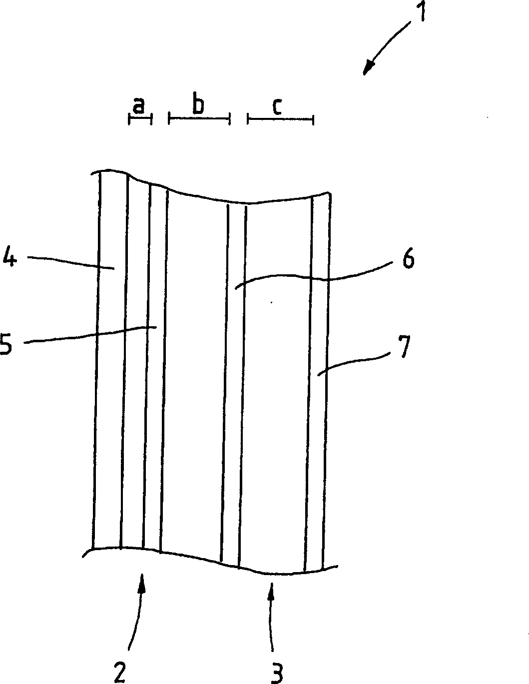
[0052] The anode base body 2 itself consists of a carrier material 4 and a coating 5, ie the active layer. The carrier material 4 is preferably stainless steel, titanium or the like, while the coating 5 is preferably made of iridium mixed oxides, platinum or the like. The coating 5 can be applied directly on the carrier material 4 or spaced apart from the carrier material 4 . in accordance with figure 1 In an exemplary embodiment, the coating 5 is spaced apart from the carrier material 4, wherein the distance between the carrier material 4 and the coating 5 is denoted by a. This distance can be, for example, a few tenths of a millimeter. in accordance with figure 1 In an exemplary embodiment, the coating 7 is applied to a substrate, which may be made of stainless steel, titanium, or the like.

[0053] Depend on figure 1 It can be seen that the separator 3 of the anode 1 is a two-part piece. The first part of the separator 3 is formed by a tissue 6 consisting of a non-con...


PUM


Abstract

A galvanic bath, especially an acidic galvanic bath, comprises an anode, a cathode and an electrolyte. The anode has two or more phases, and the electrolyte comprises more than 70 mg / l chloride and 5-5000 mg / l, especially 200-1200 mg / l of either molybdenum, vanadium, zirconium, tantalum, tungsten, hafnium or titanium in oxo-acidic anion or polyanion form, or acid anhydride cation form.

Description

technical field [0001] The present invention relates to electroplating baths, especially acid electroplating baths, comprising an anode, a cathode and an electrolyte. Background technique [0002] Electroplating baths of the above-mentioned type are known in the prior art, so that the present invention does not require separate documentary evidence. [0003] Electroplating methods such as copper, nickel, zinc or tin plating are performed with soluble or insoluble anodes. Soluble anodes, also known as active anode systems, go into solution during electrolysis. Insoluble anodes, also known as inert anode systems, do not go into solution during electrolysis and usually consist of a support material and a coating applied thereon, said coating being called the active layer. Among these, titanium, niobium, stainless steel or other inert metals are generally used as support materials, but in any case where such materials are used, they become inert under the electrolytic conditio...

Claims


Application Information

Patent Timeline
Patent Type & Authority Applications(China)
IPC IPC(8): C25D17/00C25D3/02C25D3/38C25D21/00
CPCC25D3/02C25D3/56C25D17/12
Inventor 乌尔里希·施默格尔吉恩·拉斯穆森
Owner ENTHONE INC
Why Eureka
Try Eureka