
Drum brake module which can be operated by electric motor

a technology of drum brake and electric motor, which is applied in the direction of brake system, brake drum, mechanical apparatus, etc., can solve the problems of increasing the complexity of production in this region, not allowing any simple variation in production series, etc., and achieves the elimination of any distortion, the elimination of disadvantageous effects of brake drum contracting, and the definition of the level of elasticity

Active Publication Date: 2015-11-03
CONTINENTAL TEVES AG & CO OHG
View PDF10 Cites 20 Cited by
  • Summary
  • Abstract
  • Description
  • Claims
  • Application Information

AI Technical Summary

Benefits of technology

This solution simplifies the assembly and production of drum brake modules, reduces installation space, and enhances efficiency by minimizing friction, enabling the module to function as both a parking and service brake with reduced energy requirements and no need for additional spring elements, while maintaining stability and adaptability.

Problems solved by technology

The parking brake cable pull systems having a central actuator are disadvantageous because it is necessary for the vehicle manufacturer to separately install and link the cable pull to the wheel brake, so that the process of finally assembling the actuator, actuating pull and wheel brake can only be performed at the assembly belt of the vehicle manufacturer which increases the complexity of production in this region.
In addition to an electric motor that is dimensioned in order to provide a comparatively high level of energy, this type of construction still requires further components that are embodied in an extremely special manner and therefore do not allow any simple variation in the production series.
Problems arise if the engine is switched off when the brakes are hot.

Method used


Image

  • Drum brake module which can be operated by electric motor
  • Drum brake module which can be operated by electric motor
  • Drum brake module which can be operated by electric motor

Examples


Embodiment Construction

[0029]Like features are identified in the drawing in each case by like reference numerals.

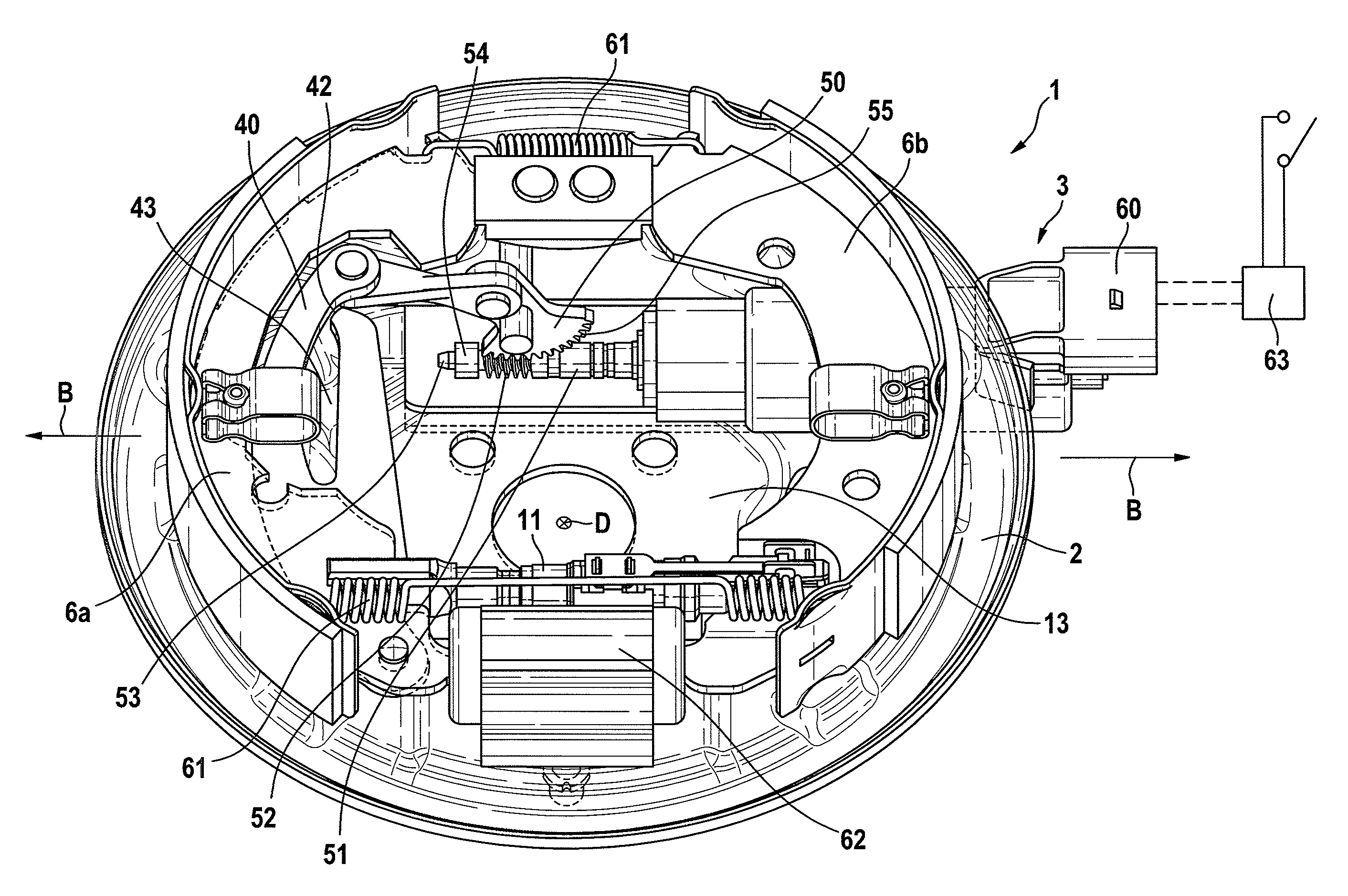
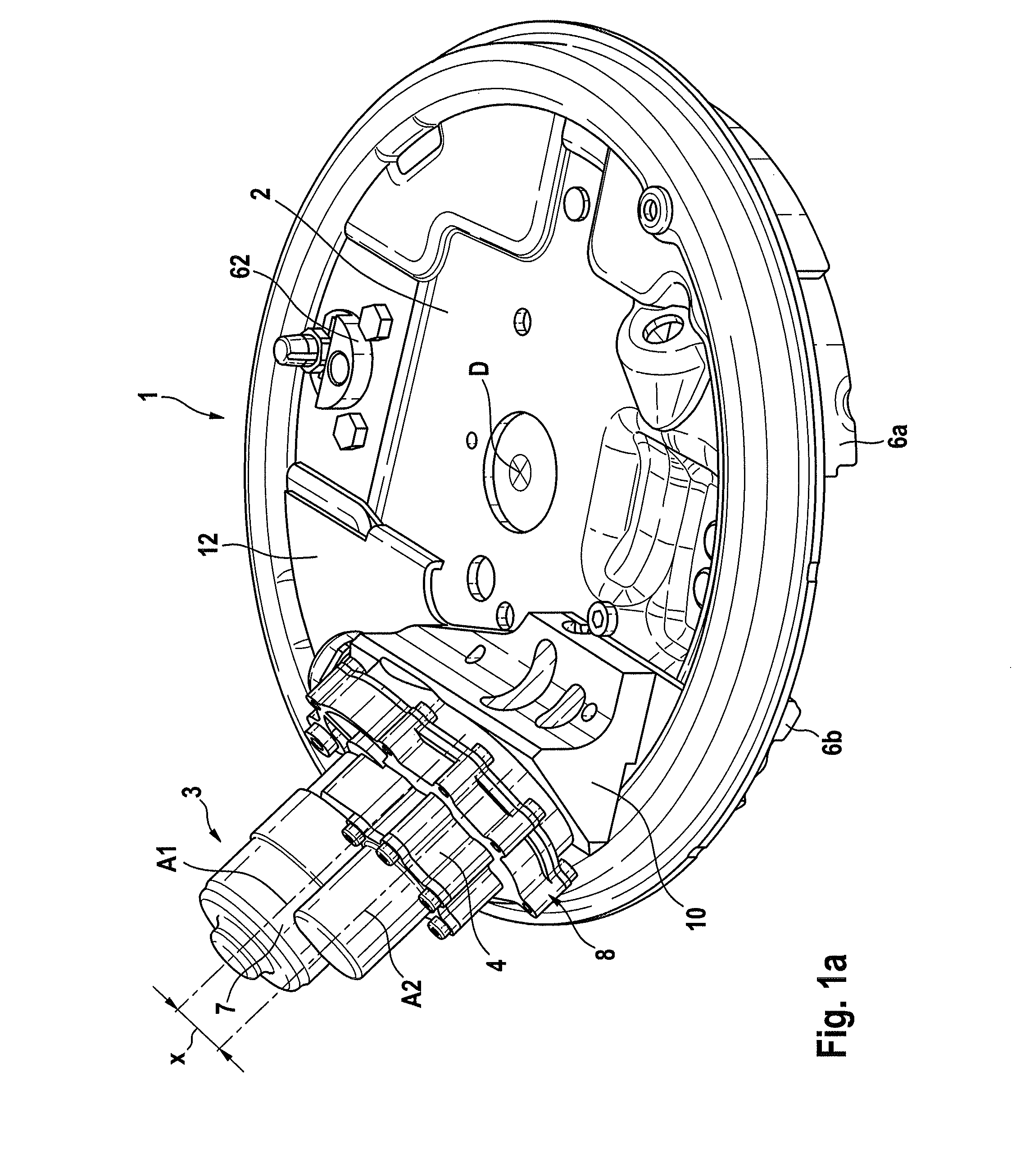
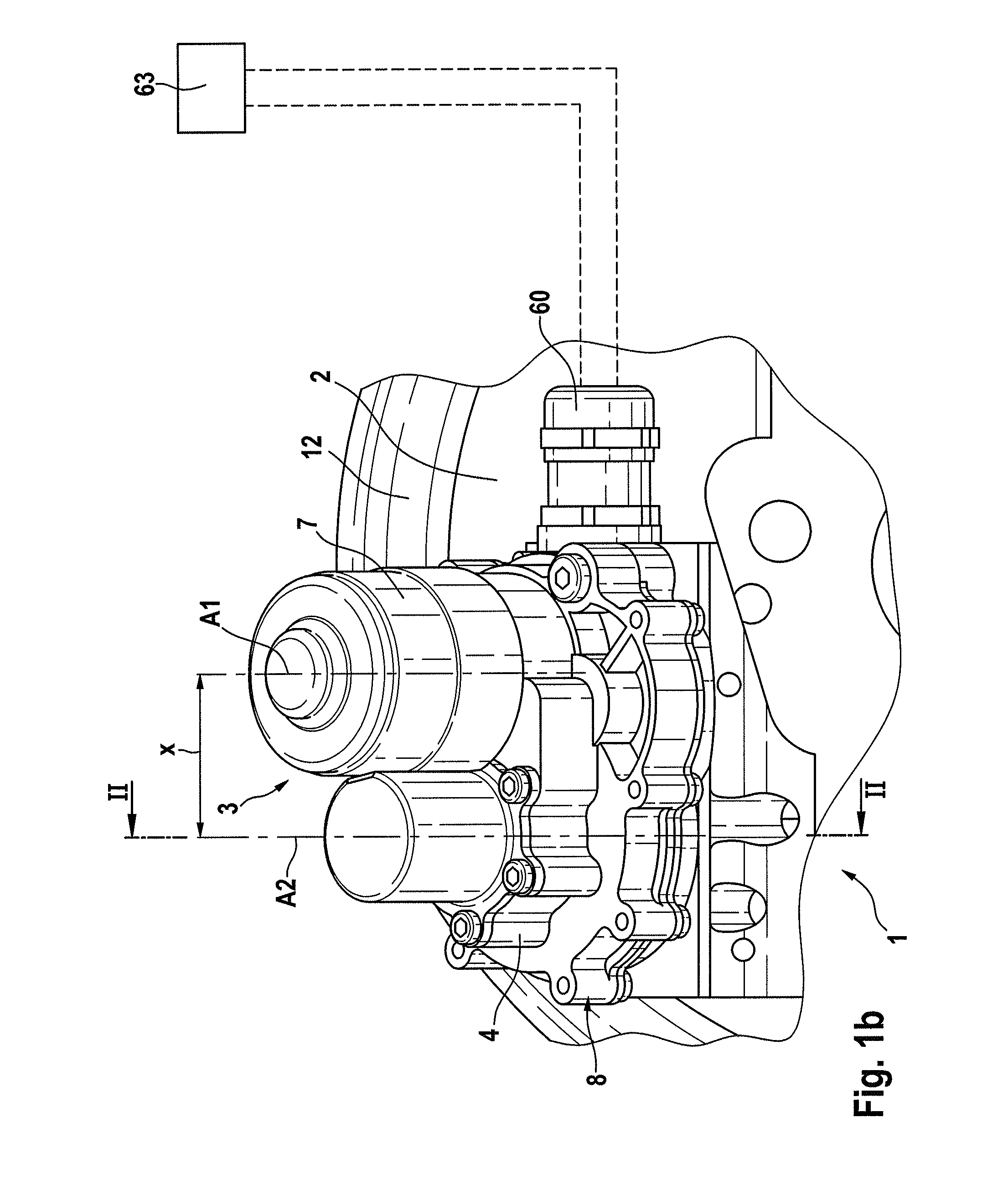
[0030]A drum brake module 1 that can be actuated by means of an electric motor and is to be arranged on axle components of a motor vehicle comprises an anchor plate 2 having brake shoes 6a,b that are mounted thereon and are provided within a brake drum that is not illustrated. An actuator 3 that is operated by an electric motor is attached to an opposite lying face of the anchor plate 2 and said actuator engages one or more of the brake shoes 6a,b by way of a gear 4 and an actuating pull 5, which is connected downstream, in such a manner that this / these brake shoe(s) 6a,b can perform an actuating movement B in the direction towards the brake drum, in order to perform the function of a service brake and / or a parking brake. A supporting device 11 can be provided between the brake shoes 6a,b.

[0031]The gear 4 comprises a gear housing 8 that receives the motor 7 or at least supports the motor 7. Th...


PUM


Abstract

A drum brake module for motor vehicles operable by electric motor and performs at least one parking brake function, having an electromechanical actuator mounted on one side of the armature plate and a rotational-translational movement converter converting a rotational drive rotational movement into a translational activation movement of brake shoes arranged on a side of the armature plate facing away from the actuator in a brake drum, and including at least one supporting device between the brake shoes such that the latter can carry out an activation movement in the direction of the brake drum. A drive nut is supported by the rotational-translational movement converter in an axially secure and rotatable fashion on the armature plate to assist the braking force. The drive nut drives a spindle arrangement mounted in a rotationally fixed and axially displaceable fashion and engages with an activation cable on at least one brake shoe.

Description

CROSS REFERENCE TO RELATED APPLICATIONS[0001]This application is the U.S. National Phase Application of PCT / EP2012 / 051805, filed Feb. 2, 2012, which claims priority to German Patent Application Nos. 10 2011 003 544.3, filed Feb. 2, 2011 and 10 2011 003 545.1, filed Feb. 2, 2011, the contents of such applications being incorporated by reference herein.FIELD OF THE INVENTION[0002]The present invention relates to a drum brake module for motor vehicles, which drum brake module can be operated by an electric motor and comprises the features of the preamble of the independent claims.BACKGROUND OF THE INVENTION[0003]A drum brake can in principle be embodied differently according to different construction principles (simplex, duplex, duo-duplex, servo, duo-servo). A uniform constructional advantage of drum brakes is their self-energizing effect in at least one direction of rotation, so that in principle it is possible to forego a brake power assist unit.[0004]In order to achieve a parking b...

Claims


Application Information

Patent Timeline
Patent Type & Authority Patents(United States)
IPC IPC(8): F16D65/10F16D51/46F16D65/16F16D51/16F16D51/10F16D65/22F16D51/18F16D51/12F16D121/24F16D125/24F16D125/40F16D125/60
CPCF16D51/10F16D51/16F16D51/46F16D65/16F16D51/12F16D51/18F16D65/22F16D2121/24F16D2125/24F16D2125/40F16D2125/60B60T13/74
Inventor BACH, UWEVON HAYN, HOLGERSUNDHEIM, RALFRITTER, WOLFGANGSEFO, AHMEDBALZ, JURGENHOFFMANN, JENSSEMSCH, MARTINMEHNER, GOTZ
Owner CONTINENTAL TEVES AG & CO OHG
Learn More