
Eye/gaze tracker and method of tracking the position of an eye and/or a gaze point of a subject

a technology of eye/gaze tracker and eye/gaze point, which is applied in the field of reliable tracking of the eyes and/or gaze points of the subject, can solve the problems of poor pupil/iris contrast, high cost and technical complexity, and suffer from motion-related errors

Active Publication Date: 2015-11-10
TOBII TECH AB
View PDF12 Cites 5 Cited by
  • Summary
  • Abstract
  • Description
  • Claims
  • Application Information

AI Technical Summary

Benefits of technology

[0010]The object of the present invention is to mitigate the above problems, and thus offer a robust eye / gaze tracking solution for a wide range of subjects irrespective of their ethnicity and the environment in which the eye / gaze tracker is used.
[0012]This eye / gaze tracker is advantageous because it provides simultaneous illumination from more than one light source without risking any undesired effects resulting from the interference between the light from the different light sources. Thus, high-quality eye / gaze tracking is enabled.
[0014]According to another preferred embodiment of this aspect of the invention the data processor is configured to derive an image quality metric describing a quality level of the image data recorded in a given interval of the at least one first or second interval. Here, the control unit is configured to produce the output signal exclusively based on image data having an image quality metric exceeding a predetermined quality threshold. Thereby, the output signal can be kept free from the influence of poor-quality eye-tracking data.
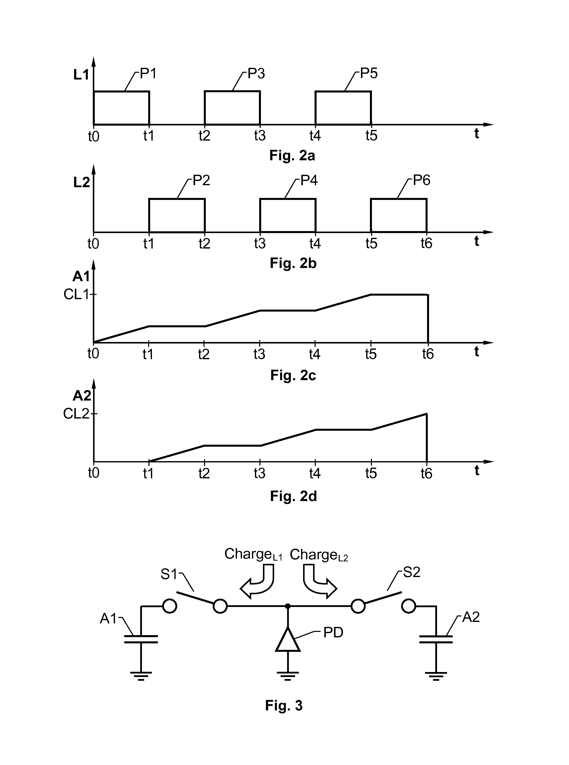
[0017]Preferably, referring to the general case above, the periodic scheme defines a sequence of illumination intervals including as many different categories of intervals as there are charge storages associated with each photodiode. This means that a subject's eye can be essentially simultaneously illuminated by light from a large number of light sources without risking that the different light sources interfere with one another in a counter-productive manner.
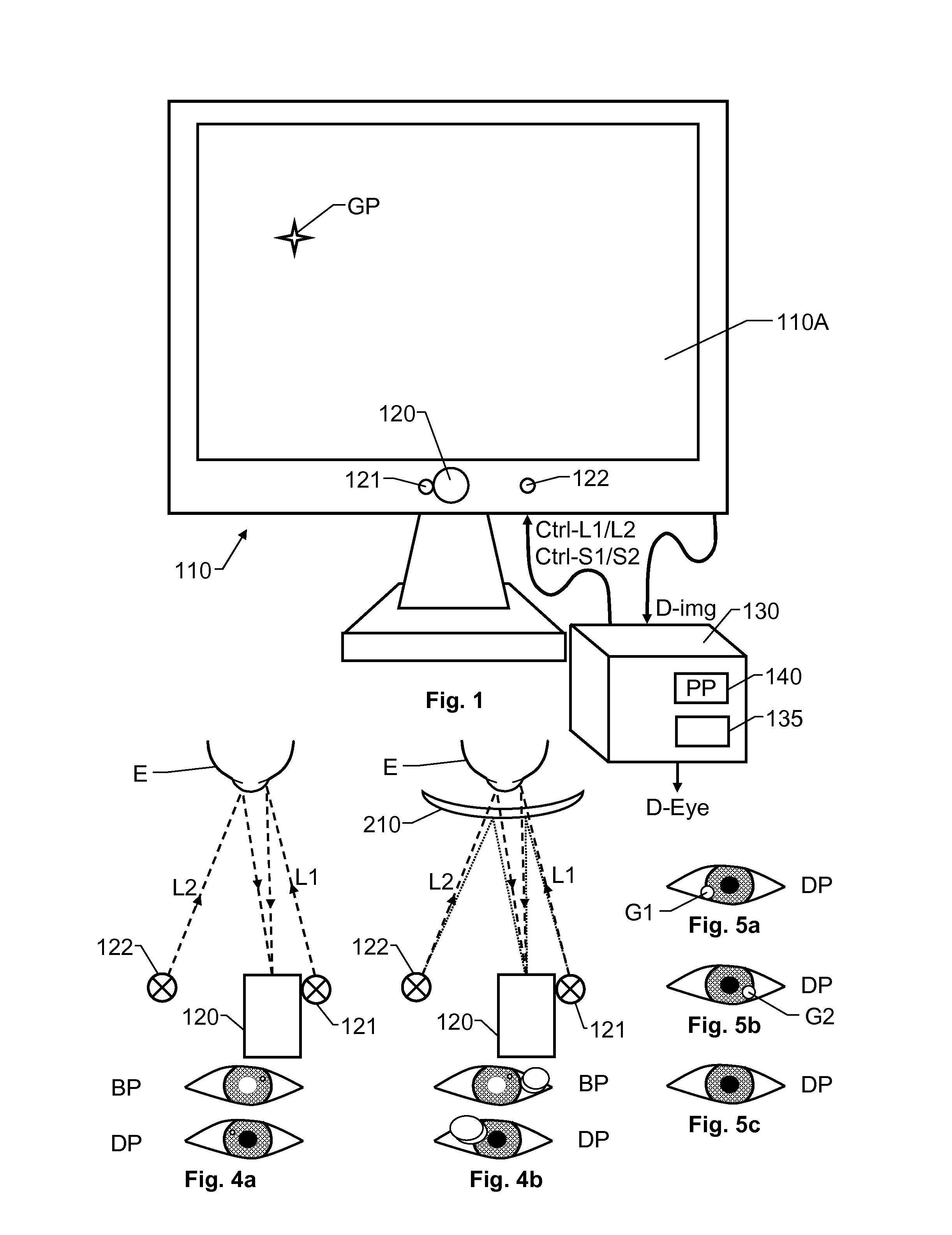
[0021]According to another preferred embodiment of this aspect of the invention a first light source is arranged at a distance to the image registering means and a stipulated operating distance between the eye / gaze tracker and the eye, such that the light emitted from the first light source is expected to cause a bright-pupil effect in the image data representing the eye; and a second light source of the light sources is arranged at a distance to the image registering means and a stipulated operating distance between the eye / gaze tracker and the eye, such that the light emitted from the second light source is expected to cause a dark-pupil effect in the image data representing the eye. This arrangement is advantageous because it facilitates automatic selection between BP or DP operation depending on which is more efficient for the subject in question.
[0023]Preferably, the first and second light sources are implemented in a common illuminator unit, which is tunable in response to a wavelength control signal so as to generate both the light at the first center wavelength and the light at the second center wavelength. The control unit is further arranged to generate the wavelength control signal and provide the common illuminator with this signal, such that the common illuminator unit is caused to generate light at the first center wavelength during the at least one first interval and generate light at the second center wavelength during the at least one second interval. Consequently, a highly compact and uncomplicated design is attained.

Problems solved by technology

The former alternative is associated with costs and technical complexity, whereas the latter suffers from motion-related errors.
However, simultaneous illumination from two or more light sources is problematic because it may result in a hybrid DP / BP effect in the registered images.
This causes a poor pupil / iris contrast.
Moreover, if the glints are located too close to one another with respect to the available resolution (due to limited optical performance, the size of the pixels or a combination thereof), the glints will blend into each other.
This causes inaccuracy when determining the center-of-glint-positions.
Additionally, such intermixed glints may obscure the pupil edge, which must be visible for accurate eye tracking algorithms.
Consequently, there are solutions for reducing the influence from ambient light, e.g. the sun, which may generate patterns and / or reflections disturbing the eye tracking algorithms and deteriorating the eye tracker performance.
However, as discussed above, several additional problems must also be addressed to improve the tracking robustness of the eye / gaze tracker.

Method used


Image

  • Eye/gaze tracker and method of tracking the position of an eye and/or a gaze point of a subject
  • Eye/gaze tracker and method of tracking the position of an eye and/or a gaze point of a subject
  • Eye/gaze tracker and method of tracking the position of an eye and/or a gaze point of a subject

Examples


first embodiment

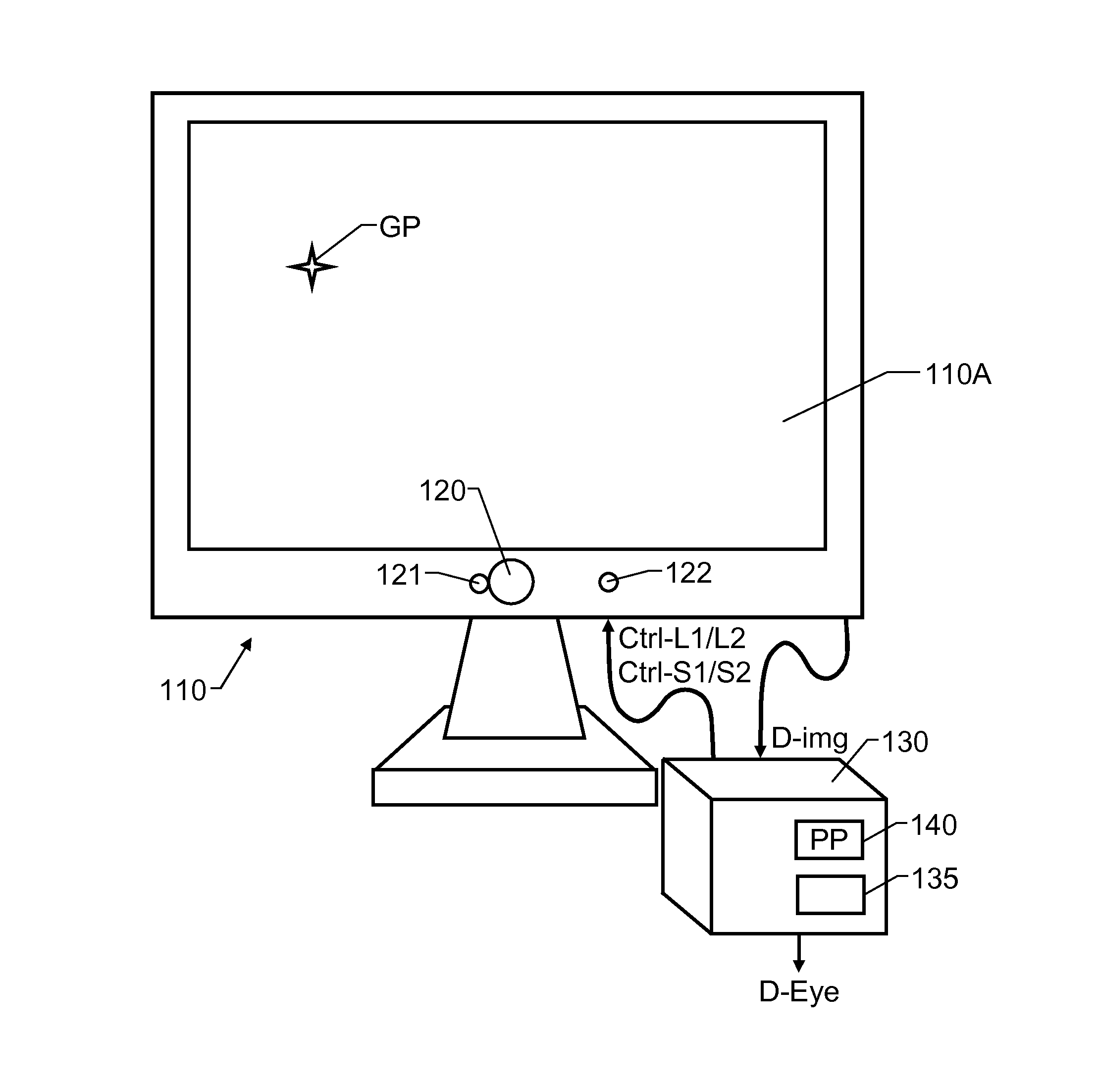
[0040]FIG. 1 shows an eye / gaze tracker according to the invention. The eye / gaze tracker includes first and second light sources 121 and 122 respectively, an image registering means 120 and a control unit 130.

[0041]Each of the first and second light sources 121 and 122 is configured to illuminate an eye E of a subject. The image registering means 120 is configured to record image data D-Img representing the eye E. The control unit 130 is configured to control the light sources 121 and 122 as well as the image registering means 120. The image registering means 120 contains an image sensor with a plurality of light sensitive elements, or pixels, which each is associated with a photodiode PD, and that are preferably arranged in a matrix, i.e. as a first number of columns and a second number of rows. For example, in a 5 megapixel sensor (having in total 5 090 816 light sensitive elements), the first number of columns may be 2 608 and the second number of rows may be 1 952. The image sens...

second embodiment

[0069]FIG. 6 shows an eye / gaze tracker according to the invention, wherein a common illuminator unit 125 implements both a first light source and a second light source. The first implemented light source is configured to emit light L1 at a first center wavelength λ1 and the second implemented light source is configured to emit light L2 at a second center wavelength λ2 which is separated from the first center wavelength λ1 by at least 60 nm. Thus, the first light source may emit light at around 850 nm and the second light source may emit light at around 940 nm.

[0070]The common illuminator unit 125 is tunable, so that, in response to a wavelength control signal Ctrl-λ1 / λ2 it generates either the light L1 at the first center wavelength λ1 or the light L2 at the second center wavelength λ2. Furthermore, the control unit 130 is arranged to generate the wavelength control signal Ctrl-λ1 / λ2 such that the common illuminator unit 125 is caused to generate light L1 at the first center wavelen...


PUM


Abstract

An eye / gaze tracker with first and second light sources each configured to illuminate an eye of a subject and controlled to selectively emit light towards the eye in such a manner that within an operation sequence the eye is illuminated by the first light source during at least one first interval and by the second light source during at least one second interval. An image sensor has a plurality of photodiodes each of which is associated with first and second charge storages configured to store electric charges based on an amount of light reaching the photodiode. At least one switch of the image sensor is controlled such that the electric charges are stored in the first charge storage as a result of the illumination during the at least one first interval and in the second charge storage as a result of the illumination during the at least one second interval.

Description

CROSS-REFERENCE TO RELATED APPLICATION[0001]This application claims priority to foreign application Great Britain 1304885.5 filed Mar. 15, 2013, the contents of which are hereby incorporated by reference herein.FIELD OF THE INVENTION[0002]The present invention relates generally to reliable tracking of a subject's eyes and / or gaze point.BACKGROUND OF THE INVENTION AND PRIOR ART[0003]High-performance eye tracking systems often use active illumination of a subject's eyes. This typically means that one or more light sources emit near-infrared light and one or more cameras capture images of the illuminated eyes. In the captured images, various features are extracted, such as the specular reflections of the illumination light source on the cornea (so-called glints) and / or the position of the pupil relative to the position of the eye.[0004]There are two principal illumination strategies, which differ in how the pupil appears in the captured images. If the light source is located close to t...

Claims


Application Information

Patent Timeline
Patent Type & Authority Patents(United States)
IPC IPC(8): A61B3/14A61B3/00G06F3/01G06K9/00A61B3/113
CPCA61B3/113G06F3/013G06K9/00604G06V40/19
Inventor SKOGO, MARTENJONSSON, HENRIKELVESJO, JOHN
Owner TOBII TECH AB
Learn More