Compensation method and device for tracking operation of optical storage system

a technology of optical storage system and compensation method, which is applied in the direction of digital signal error detection/correction, instruments, recording signal processing, etc., can solve problems such as runout associated, and achieve the effect of speeding up tracking

Active Publication Date: 2011-03-22
TIAN HLDG LLC
View PDF10 Cites 0 Cited by
  • Summary
  • Abstract
  • Description
  • Claims
  • Application Information

AI Technical Summary

Benefits of technology

[0006]It is an object of the present invention to provide a method and a device for compensating a tracking operation of a computer storage system to simultaneously compensate some operating parameters in addition to runout in order to speed up tracking.
[0007]It is another object of the present invention to provide a tracking output signal generator for increasing tracking performance of an optical disk drive by compensating some operating parameters in advance.

Problems solved by technology

Firstly, a runout associated with a relative motion between the pickup head and the storage medium is obtained when the optical pick head is in a status of focus-on but not track-on.

Method used


Image

  • Compensation method and device for tracking operation of optical storage system
  • Compensation method and device for tracking operation of optical storage system
  • Compensation method and device for tracking operation of optical storage system

Examples


Embodiment Construction

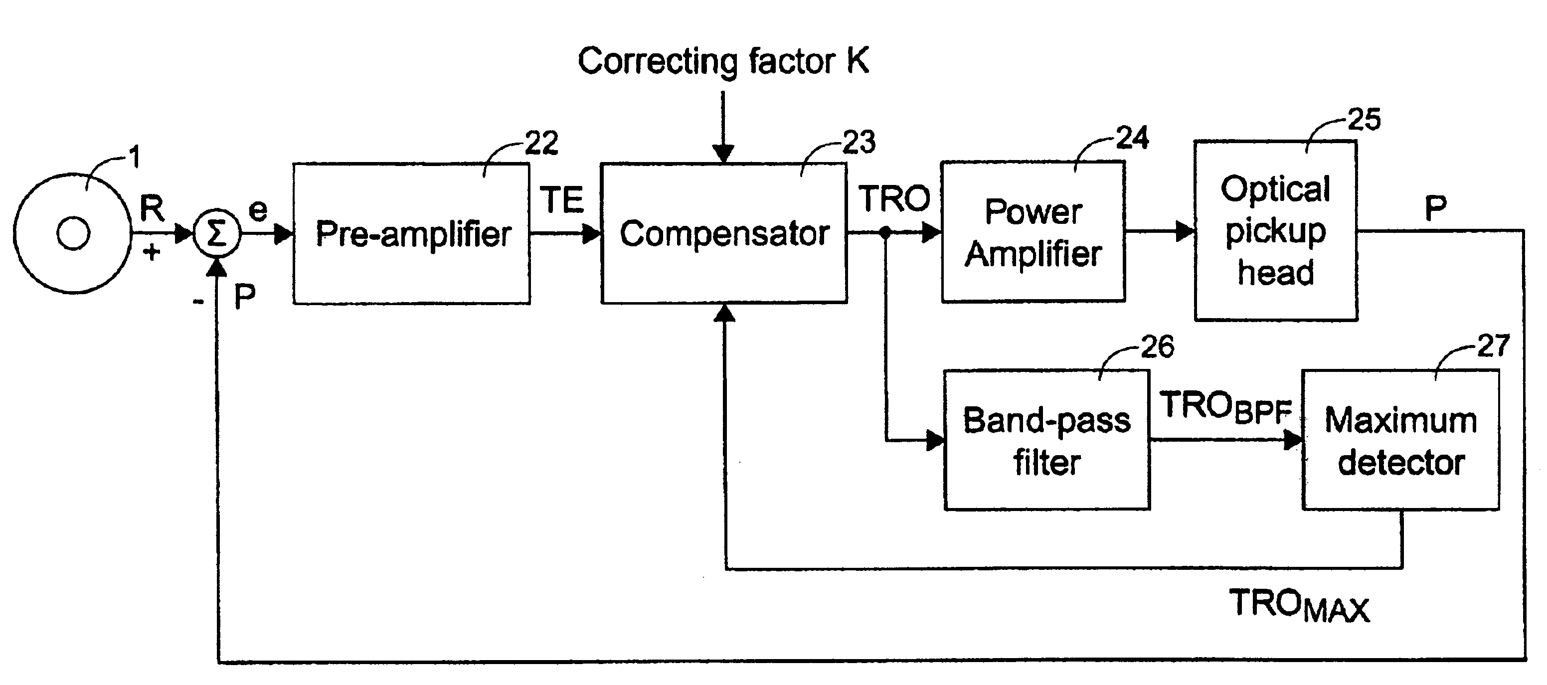
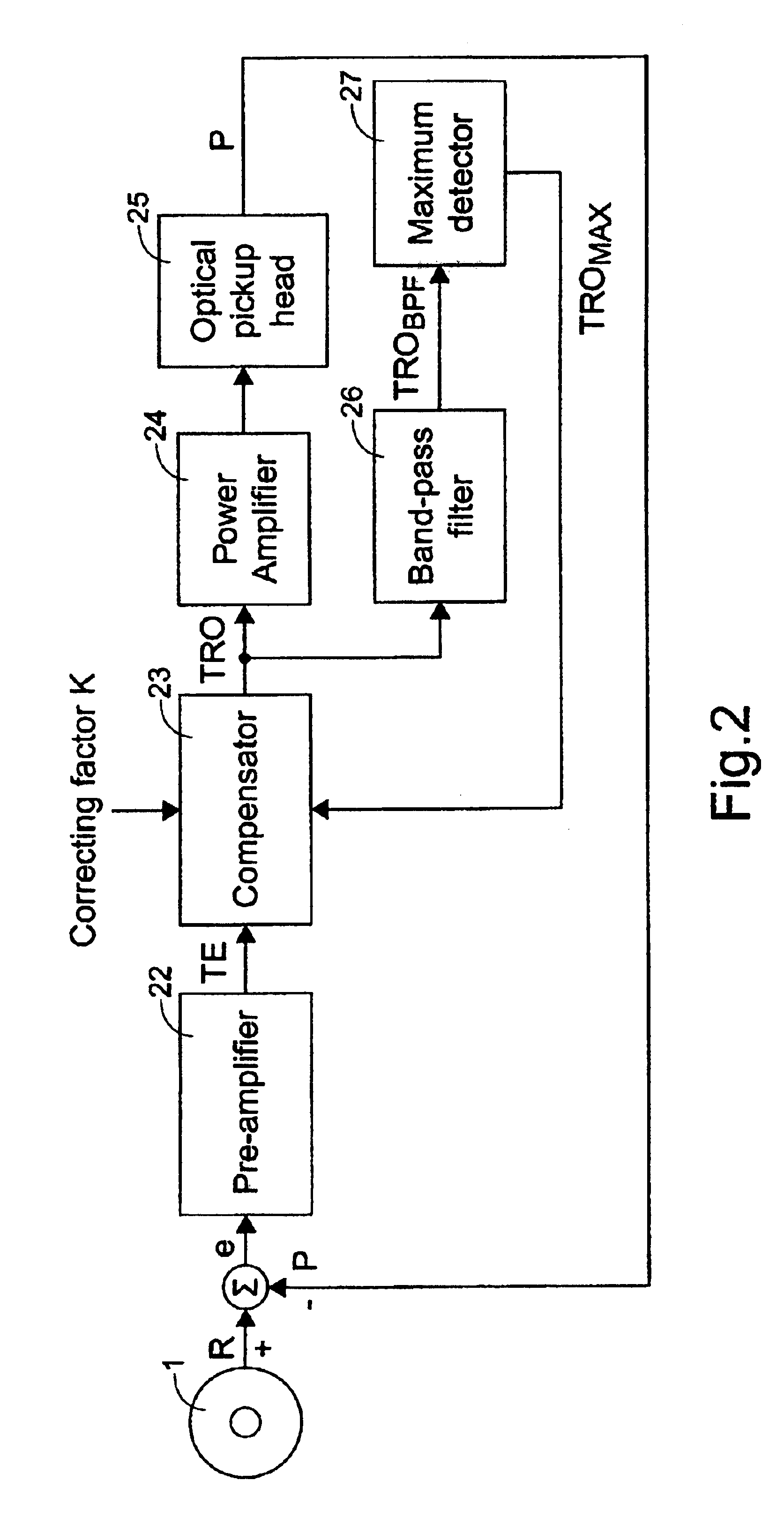
[0030]Please refer to FIG. 2, which illustrates an optical storage system according to a preferred embodiment of the present invention. The optical storage system of FIG. 2 is a control device of an optical disc drive, which includes a pre-amplifier 22, a compensator 23, a power amplifier 24, an optical pickup head 25, a band-pass filter 26, and a maximum detector 27. The optical pickup head 25 picks up data from an optical disc 1. During operation, an error signal e between the position P of the optical pickup head 25 relative to the disc and the runout R is processed by the pre-amplifier 22 to generate a tracking error TE. The tracking error TE is transmitted to the compensator 23, e.g. a digital signal processor (DSP), to be processed into a tracking output signal TRO, which is next delivered into two separate paths for further processing. In a normal operation procedure, the pre-amplifier 22, compensator 23, power amplifier 24 and the optical pickup head 25 form a close loop, so...


PUM

PropertyMeasurementUnit
speedaaaaaaaaaa
structuresaaaaaaaaaa

Abstract

An optical storage system includes a pickup head for picking up data from a storage medium. Firstly, the maxima of a tracking error signal and runout are obtained in a calibration procedure in a close loop formed by an optical pickup head, a pre-amplifier, a compensator, a band-pass filter and a maximum detector. A calibration factor is then defined and derived by using the obtained maxima and nominal factors of a power amplifier and the optical pickup head of the optical storage system. The path formed by the series-connected band-pass filter and maximum detector is then disabled, while the calculated calibration factor is then stored in the compensator. The optical storage system may operate in a close loop formed by the optical pick head, pre-amplifier, compensator, a power amplifier under a normal operation procedure so that the optical storage system may record or read data onto / from an optical disc under the compensation provided by the calibration factor.

Description

FIELD OF THE INVENTION[0001]The present invention relates to a method for compensating a tracking operation of an optical storage system, and more particularly to a method for compensating a tracking operation of a pickup head of an optical storage system. The present invention also relates to a device for compensating a tracking operation of an optical pickup head of an optical storage system.BACKGROUND OF THE INVENTION[0002]Optical storage systems record digital data onto the surface of a storage medium, which is typically in the form of a rotating magnetic or optical disc, by altering a surface characteristic of the disc. The digital data serves to modulate the operation of a write transducer (write head), which records binary sequences onto the disc in radially concentric or spiral tracks. When reading this recorded data, a read transducer (read head), positioned in close proximity to the rotating disc, detects the alterations on the medium and generates a sequence of correspond...

Claims


Application Information

Patent Timeline
Patent Type & Authority Patents(United States)
IPC IPC(8): G11B7/00G11B7/09G11B7/095
CPCG11B7/0945G11B7/0953
Inventor CHU, MENG H.
Owner TIAN HLDG LLC
Why Eureka
Try Eureka