Apparatus, system and method for compression testing of test specimens

a technology of apparatus and test specimen, applied in the direction of optical apparatus testing, structural/machine measurement, instruments, etc., can solve the problems of increased time and expense of testing, increased flow time, and thin base portion b>22/b>,

Active Publication Date: 2015-11-10
THE BOEING CO
View PDF6 Cites 4 Cited by
  • Summary
  • Abstract
  • Description
  • Claims
  • Application Information

AI Technical Summary

Benefits of technology

[0013]This need for an improved apparatus, system and method for compression testing of test specimens, such as large notch compression test panels of component parts of air vehicles is satisfied by this disclosure. As discussed in the below detailed description, embodiments of the improved apparatus, system and method for compression testing of test specimens, such as large notch compression test panels of component parts of air vehicles, may provide significant advantages over known apparatus assemblies, systems and methods.
[0014]In one embodiment of the disclosure, there is provided an apparatus for compression testing. The apparatus comprises a base assembly having an end load element attached to the base assembly, the base assembly being rigid. The apparatus further comprises a support assembly attached to the base assembly, the support assembly having a plurality of window portions. The apparatus further comprises a core assembly installed within the support assembly, the core assembly being crushable and configured to protect the support assembly and the base assembly from fracture loads generated during compression testing.
[0016]In another embodiment of the disclosure, there is provided a system for compression testing. The system comprises an apparatus for compression testing. The apparatus comprises a base assembly having an end load element attached to the base assembly, the base assembly being rigid. The apparatus further comprises a support assembly attached to the base assembly, the support assembly having a plurality of window portions. The apparatus further comprises a core assembly installed within the support assembly, the core assembly being crushable and configured to protect the support assembly and the base assembly from fracture loads generated during compression testing.
[0019]In another embodiment of the disclosure, there is provided a method for compression testing. The method comprises the step of forming an apparatus for compression testing of a test specimen. The apparatus comprises a base assembly having an end load element attached to the base assembly, the base assembly being rigid. The apparatus further comprises a support assembly attached to the base assembly, the support assembly having a plurality of window portions. The apparatus further comprises a core assembly installed within the support assembly, the core assembly being crushable and configured to protect the support assembly and the base assembly from fracture loads generated during compression testing.

Problems solved by technology

However, the use of such strain gages 14 (see FIG. 1) may involve extensive installation time and labor, which results in increased flow time.
This may, in turn, result in increased time and expense of testing.
However, the base portion 22 may be thin and wear out after several compression tests.
However, such shimming process may involve extensive installation time and labor prior to testing.
This may, in turn, result in increased time and expense of testing.
Thus, existing methods for compression testing of test specimen panels, such as large notch compression panels, may be expensive and may take four (4) to ten (10) weeks or more to complete.

Method used


Image

  • Apparatus, system and method for compression testing of test specimens
  • Apparatus, system and method for compression testing of test specimens
  • Apparatus, system and method for compression testing of test specimens

Examples


Embodiment Construction

[0047]Disclosed embodiments will now be described more fully hereinafter with reference to the accompanying drawings, in which some, but not all of the disclosed embodiments are shown. Indeed, several different embodiments may be provided and should not be construed as limited to the embodiments set forth herein. Rather, these embodiments are provided so that this disclosure will be thorough and will fully convey the scope of the disclosure to those skilled in the art.

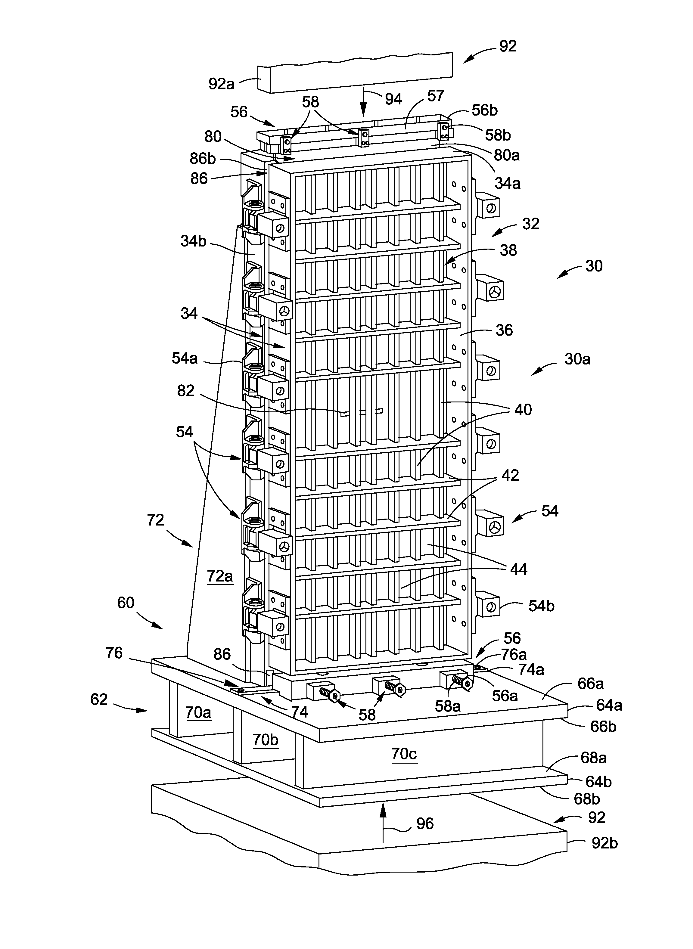
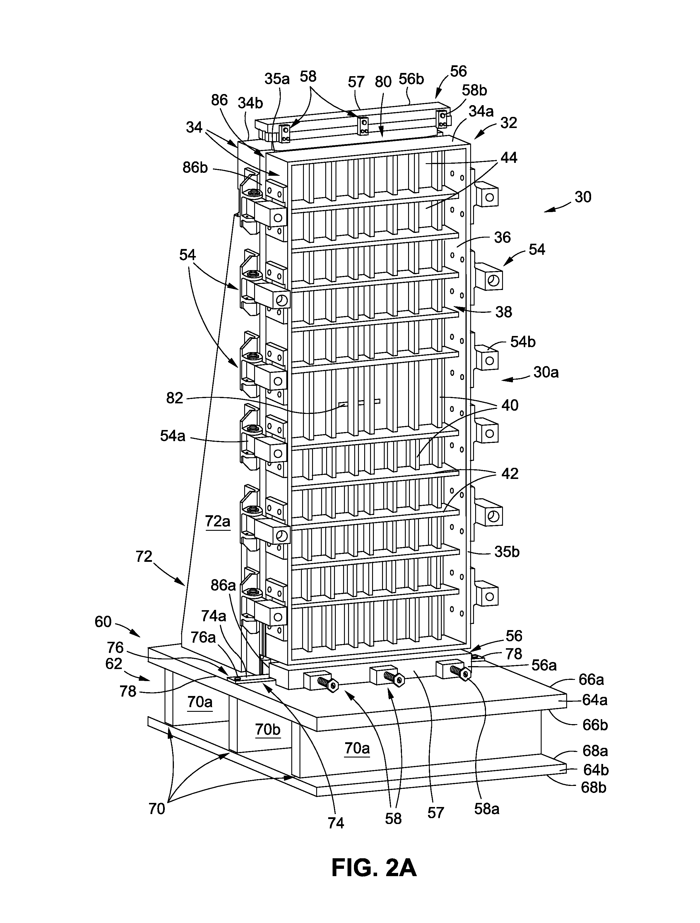
[0048]Now referring to the Figures, FIG. 2A is an illustration of a front perspective view of an exemplary embodiment of an apparatus 30 for compression testing of a test specimen 80 (see FIG. 2H) of the disclosure. FIG. 2B is an illustration of a back perspective view of the apparatus 30 of FIG. 2A. As shown in FIGS. 2A-2B, the apparatus 30 may be in the form of a test fixture 30a, such as, for example, a large notch compression test fixture.

[0049]As shown in FIGS. 2A, 2H, the test specimen 80 may be in the form of a ...


PUM

PropertyMeasurementUnit
lengthaaaaaaaaaa
lengthaaaaaaaaaa
lengthaaaaaaaaaa

Abstract

There is provided an apparatus for compression testing. The apparatus has a base assembly having an end load element attached to the base assembly, the base assembly being rigid. The apparatus has a support assembly attached to the base assembly, and having a plurality of window portions. The apparatus has a core assembly installed within the support assembly, the core assembly being crushable and configured to protect the support assembly and the base assembly from fracture loads generated during compression testing. The base assembly, the support assembly, and the core assembly together form an apparatus for compression testing of a test specimen having a notch portion. The apparatus is configured for use with an optical strain measurement system. When the test specimen is installed in the support assembly, the test specimen and the notch portion are visible to the optical strain measurement system through the plurality of window portions.

Description

BACKGROUND[0001]1) Field of the Disclosure[0002]The disclosure relates generally to apparatus assemblies, systems and methods for compression testing of test specimens, and more particularly, to apparatus assemblies, systems and methods for compression testing of large notch compression test panels, such as panels of component parts of air vehicles.[0003]2) Description of Related Art[0004]Mechanical testing of component parts, or of test specimens of component parts, is often performed in the manufacture of air vehicles, such as aircraft, rotorcraft, spacecraft, and other air vehicles. Mechanical testing provides material property data, such as strength, hardness ductility, and other data about the material as tested under various conditions, such as compression, tension, load and temperature. In turn, the mechanical testing provides information relating to the suitability of a material for its intended application. Such information aids in the design of component parts that will pe...

Claims


Application Information

Patent Timeline
Patent Type & Authority Patents(United States)
IPC IPC(8): G01N3/02G01M5/00G01N3/04G01N3/08G01M11/08
CPCG01N3/02G01M5/005G01M5/0091G01M11/081G01N3/04G01N3/08G01N2203/0003G01N2203/0019G01N2203/027G01N2203/0282G01N2203/0447G01N2203/0641G01N2203/001
Inventor KISMARTON, MAX U.GRIESS, KENNETH H.
Owner THE BOEING CO
Why Eureka
Try Eureka