Shock absorbing structure of propeller shaft

a technology of propeller shaft and shock absorption, which is applied in the direction of shaft and bearing, yielding coupling, rotary machine parts, etc., can solve the problems of protruding portion breaking, protruding portion chipping or breaking, and protruding portion breaking, so as to prevent and preventing a protruding portion from breaking

Inactive Publication Date: 2010-05-18
SHOWA CORP
View PDF4 Cites 3 Cited by
  • Summary
  • Abstract
  • Description
  • Claims
  • Application Information

AI Technical Summary

Benefits of technology

[0006]Accordingly, the present invention is made by taking the circumstances mentioned above into consideration, and an object of the present invention is to provide a shock absorbing structure of a propeller shaft which can prevent a chip, a crack, a fracture and the like of the protruding portion, and can stabilize a breaking load of the protruding portion.
[0009]In accordance with the present invention, it is possible to prevent a chip, a crack, a fracture and the like of the protruding portion, and it is possible to stabilize a breaking load of the protruding portion.

Problems solved by technology

In this case, in the shock absorbing structure of the propeller shaft mentioned above, a thickness of the protruding portion is small, and in the case that an induction hardening is applied, there is a risk that the protruding portion gets chipped or is broken at a time of carrying the coupling member or assembling the propeller shaft.
Further, there is a problem that a crack is generated in the protruding portion at a time of hardening.
Further, when the tripod pressed by the outer race is brought into contact with the protruding portion and comes into collision with the protruding portion, the tripod and the protruding portion are brought into contact with each other and the protruding portion is broken.
Accordingly, there is a problem that a dispersion is generated in a breaking load of the protruding portion due to a dimensional error of the thickness of the protruding portion, a dimensional error of the tripod, an error of a fitting frictional force of the tripod with respect to the inner shaft, or the like.

Method used


Image

  • Shock absorbing structure of propeller shaft
  • Shock absorbing structure of propeller shaft
  • Shock absorbing structure of propeller shaft

Examples


Embodiment Construction

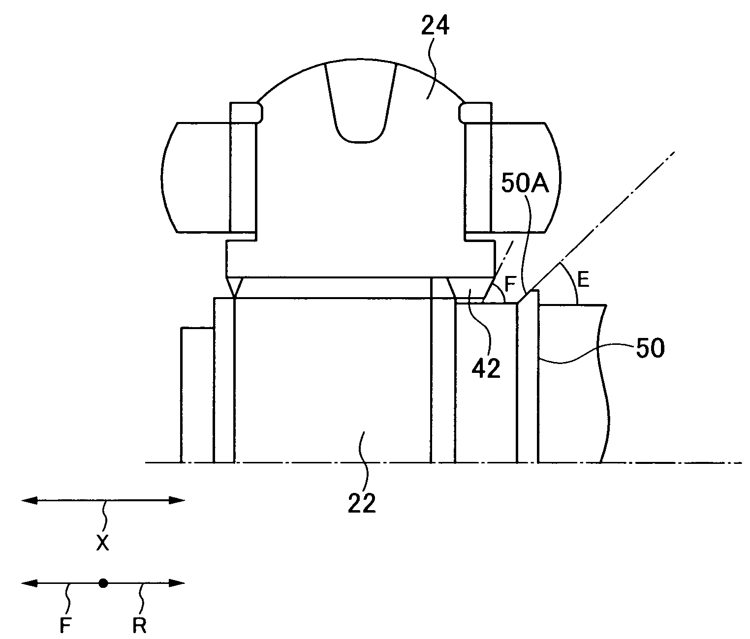
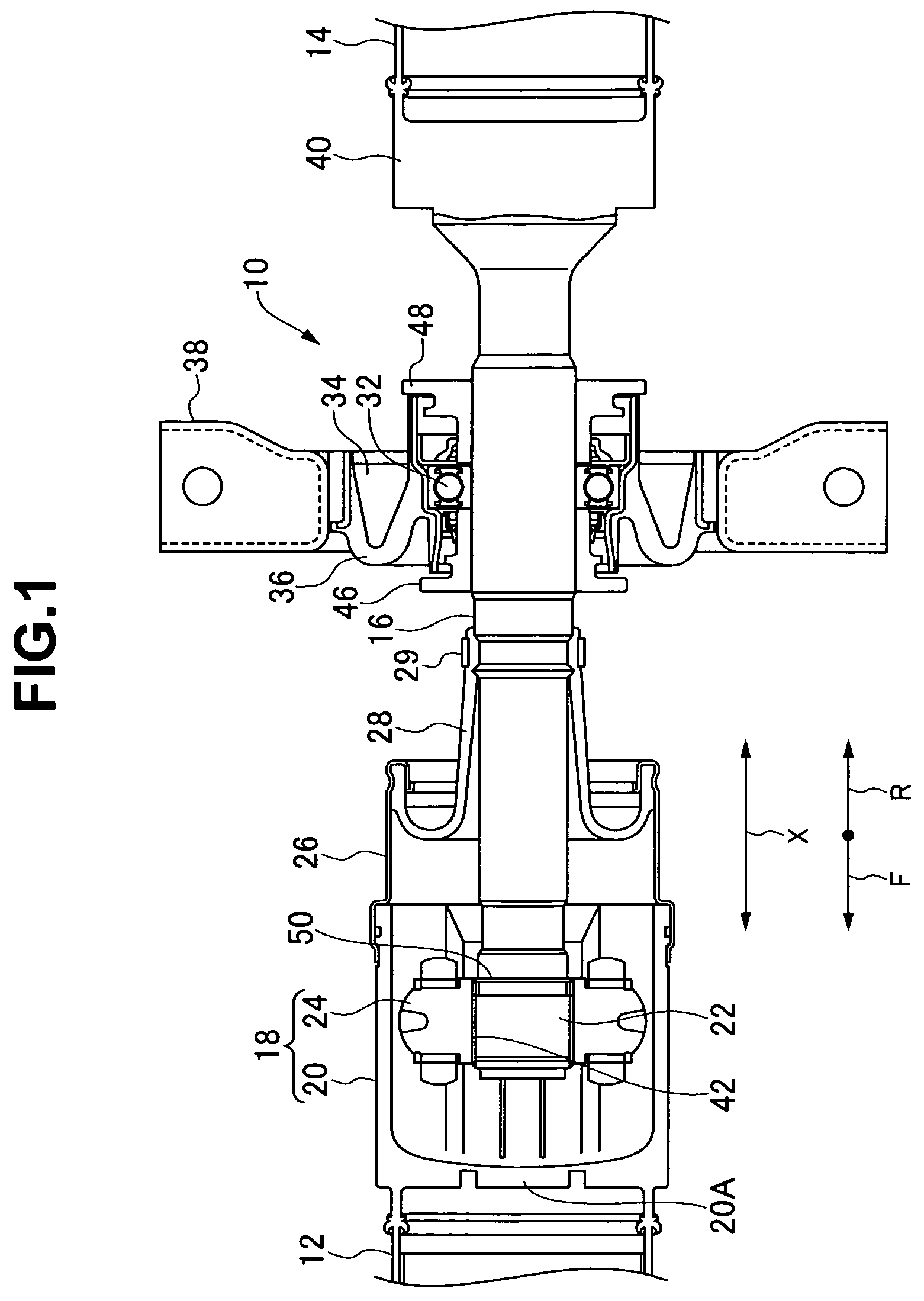
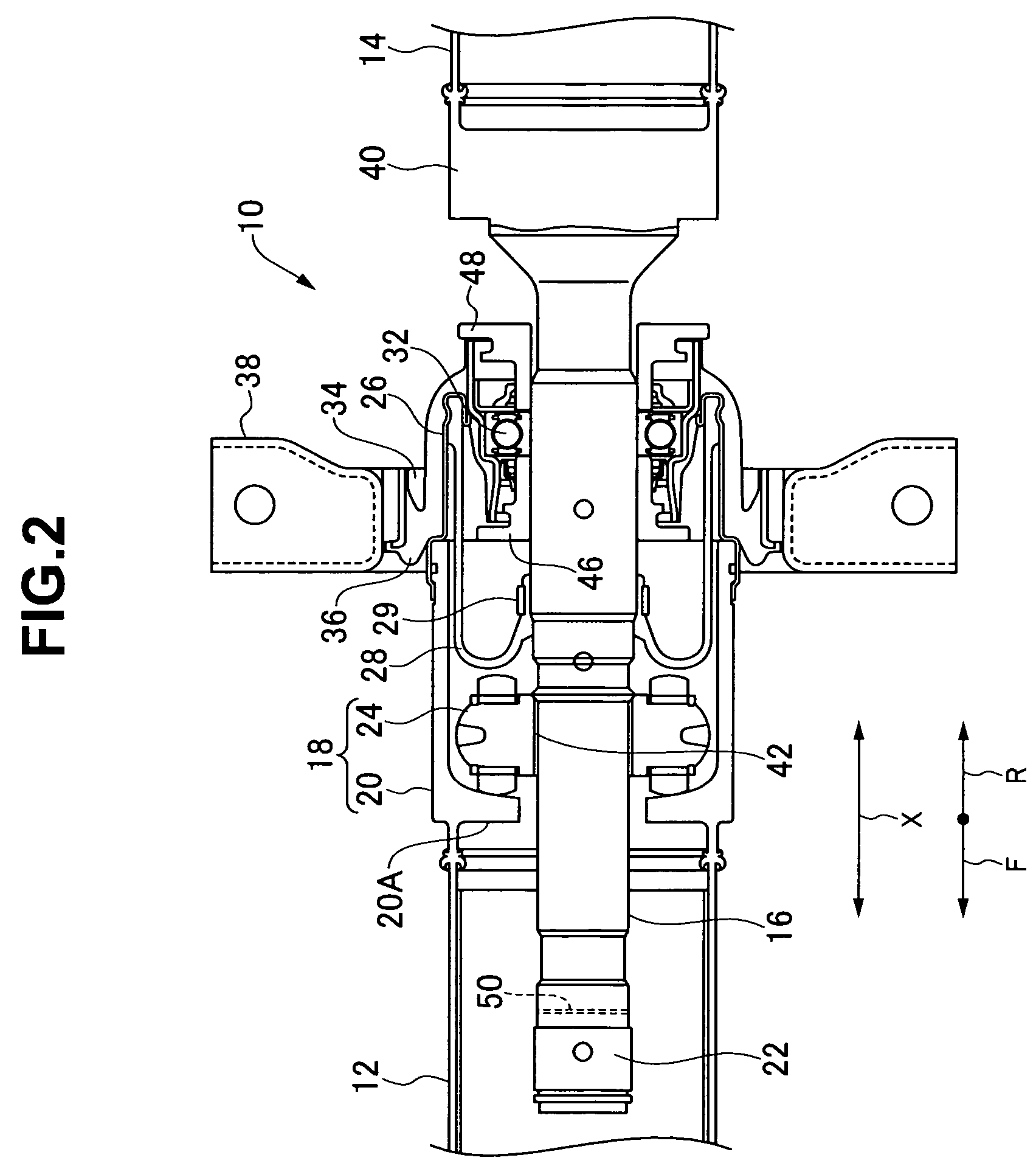
[0015]Next, a description will be given of a shock absorbing structure of a propeller shaft in accordance with an embodiment of the present invention with reference to the accompanying drawings.

[0016]As shown in FIGS. 1 and 2, a shock absorbing structure 10 of a propeller shaft in accordance with the present embodiment is provided with an approximately cylindrical first propeller shaft 12 positioned in an internal combustion engine side of an FF base. One end (a front end) of the first propeller shaft 12 is coupled to an output side of the internal combustion engine via a cross joint (not shown).

[0017]Further, the shock absorbing structure 10 of the propeller shaft is provided with an approximately cylindrical second propeller shaft 14 positioned in a rear wheel side. A rear end of the second propeller shaft 14 is coupled to a differential gear (not shown) via a universal joint (not shown). Further, a coupling shaft 16 is provided between the first propeller shaft 12 and the second ...


PUM


Abstract

When an inner ring portion of a tripod is brought into contact with a protruding portion, the inner ring portion is brought into contact with the protruding portion because an outer diameter of the protruding portion is smaller than a diameter of a tilted outer end portion of the inner ring portion. Since the inner ring portion is tilted with respect to an axial direction, the inner ring portion is brought into contact with the protruding portion by a point (a line) not by a surface. If the inner ring portion is brought into contact with the protruding portion by the point, a stress concentration is generated at the point with which the protruding portion is brought into contact, a small impact force overcomes a breaking load of the protruding portion in the stress concentration portion, and the stress concentration portion is easily broken (plastically deformed). Accordingly, it is possible to easily break the protruding portion, and even if there is a dimensional error of the protruding portion or the like, it is possible to make a load breaking the protruding portion approximately constant.

Description

BACKGROUND OF THE INVENTION[0001]1. Field of the Invention[0002]The present invention relates to a shock absorbing structure of a propeller shaft used for a vehicle or the like.[0003]2. Description of the Related Art[0004]In a conventional shock absorbing structure of a propeller shaft, there is a structure in which an outer race of a tripod universal joint is formed in a rear end of a first propeller shaft, an inner shaft portion is formed in a front portion of a coupling member, tripods corresponding to three bearings protruding in a radial direction is spline fitted to a leading end portion of the inner shaft portion, and the respective tripods are slidably fitted to three grooves formed on a cylindrical inner peripheral surface of the outer race while being directed in an axial direction so as to structure the tripod universal joint, thereby executing a power transmission at a constant velocity (refer to Japanese Patent Application Laid-open No. 10-250390 (patent document 1)). A...

Claims


Application Information

Patent Timeline
Patent Type & Authority Patents(United States)
IPC IPC(8): F16D3/205
CPCF16D3/2055Y10S464/905
Inventor HIRAKAWA, JUNICHI
Owner SHOWA CORP
Why Eureka
Try Eureka