Varying capacitance rotating electrical machine

a technology of rotating electrical machines and capacitance, which is applied in the direction of piezoelectric/electrostrictive device details, piezoelectric/electrostrictive/magnetostrictive devices, and influence generators, etc., can solve the problem of low power density, and achieve reasonable manufacturing tolerances and increase the power density of the device

Active Publication Date: 2015-11-10
WISCONSIN ALUMNI RES FOUND
View PDF20 Cites 10 Cited by
  • Summary
  • Abstract
  • Description
  • Claims
  • Application Information

AI Technical Summary

Benefits of technology

[0004]The present invention provides a varying capacitance rotating electrical machine in which capacitive coupling is obtained between rotating and stationary capacitor plates by allowing one plate to float on a cushion of fluid, generated by the relative motion of the plates, in the manner of an air bearing. The small gaps between the plates, achievable with reasonable manufacturing tolerances, greatly increase the power density of the device.
[0006]It is thus a feature of at least one embodiment of the invention to provide high power densities for varying capacitance motors by allowing closer coupling of the capacitive plates. By floating the capacitive plates on a cushion of air, dimensional variations resulting from wear or manufacturing tolerances may be accommodated.
[0008]It is thus a feature of at least one embodiment of the invention to provide a simple design borrowing from the principles of an air bearing.
[0010]It is thus a feature of at least one embodiment of the invention to provide a system using an incompressible material offering improved mechanical stability and / or higher separation forces.
[0014]It is thus a feature of at least one embodiment of the invention to provide a simple rotor mechanism employing conductive plates that move into alignment and out of alignment with changes in the capacitance.
[0016]It is thus a feature of at least one embodiment of the invention to provide a simple configuration in which the varying capacitance is defined by one or more elements having only two components subject to relative displacement.

Problems solved by technology

An obstacle to the development of varying capacitance rotating electrical machines is the relatively low capacitive coupling that can be obtained between the stator and rotor resulting in low power density (e.g. the need for physically large devices for a given power level).

Method used


Image

  • Varying capacitance rotating electrical machine
  • Varying capacitance rotating electrical machine
  • Varying capacitance rotating electrical machine

Examples


Embodiment Construction

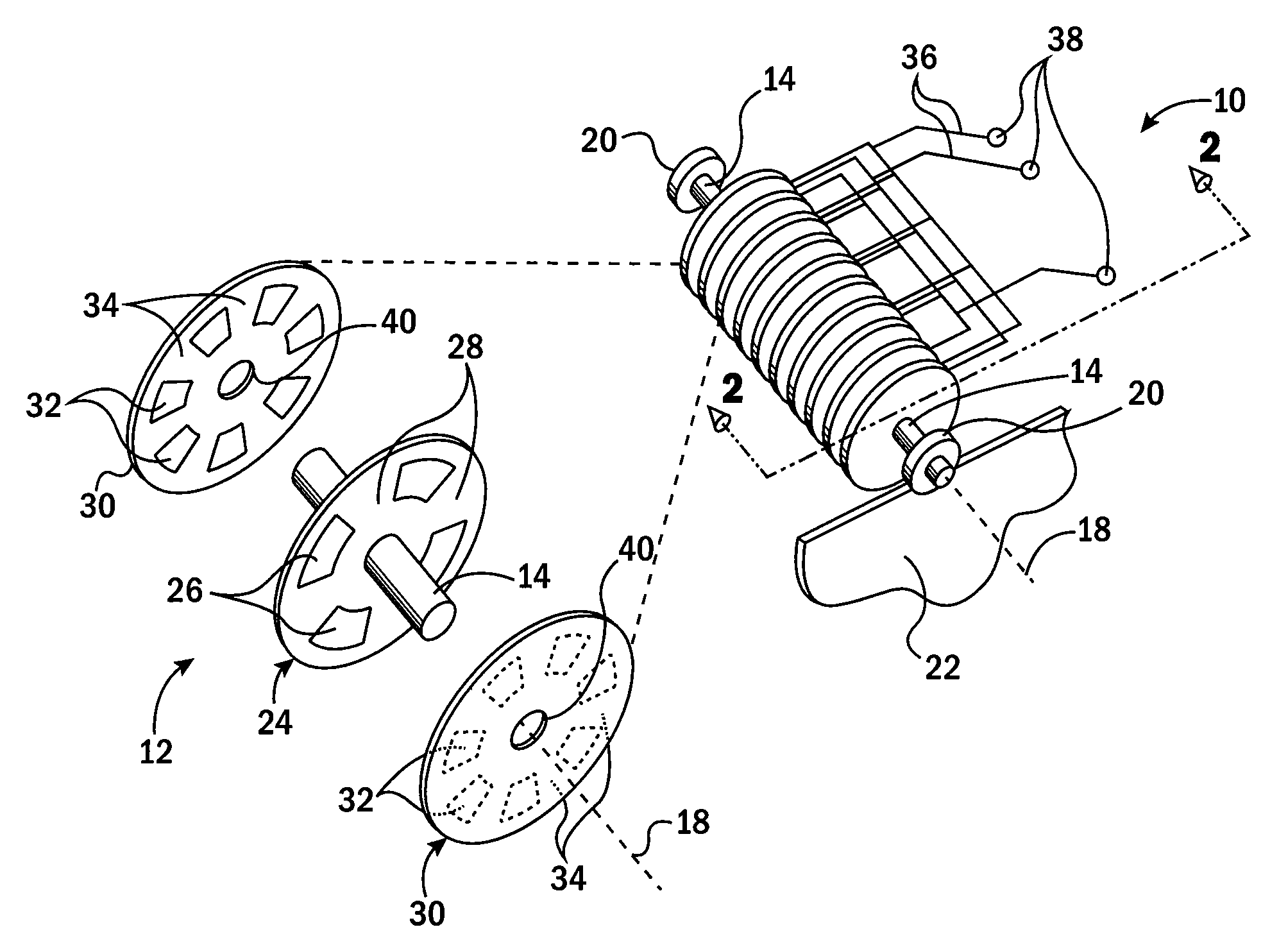
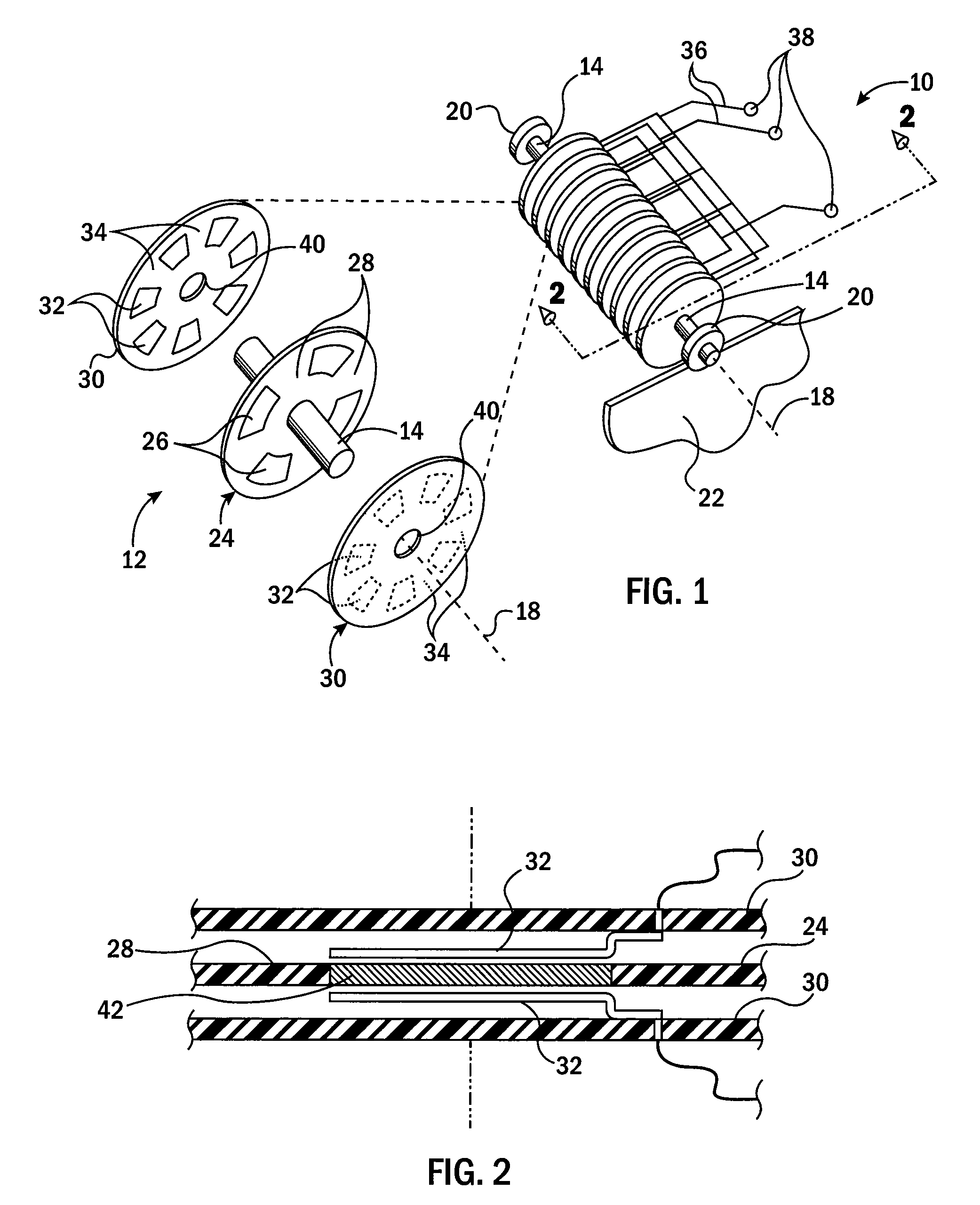
[0046]Referring now to FIG. 1, in one embodiment, a rotating electrical machine 10 per the present invention may provide a rotor 12 mounted on an axle 14 for rotation about an axis 18. The axle 14 may be supported at opposite ends by bearings 20 supported by a frame 22, the latter being generally stationary.

[0047]The rotor 12 may support one or more rotor disks 24 extending generally perpendicularly to the axis 18 to rotate with the axle 14. Front and rear surfaces of the rotor disks 24 made be divided into plate areas 26 and non-plate areas 28 spaced circumferentially therearound the axis 18. In this embodiment, plate areas 26 may be conductive plates on the opposite side of the rotor disks 24 and electrically joined through the rotor disk 24 or provided a continuous conductive or high dielectric material extending through the axial thickness of the rotor disk 24.

[0048]Flanking each rotor disk 24 along the axis 18 are two stator disks 30 having plates 32 separated and electrically ...


PUM


Abstract

A varying capacitance rotating electrical machine provides capacitor elements, such as capacitor plates, that move with respect to each other as separated by a thin film of fluid, for example air, on which one capacitor element floats. In one embodiment, multiple plates provide for three-phase operation. Narrow gaps provided by the floating capacitor elements increase the power density of rotating electrical machine.

Description

BACKGROUND OF THE INVENTION[0001]The present invention relates to rotating electrical machines (e.g. electrical motors and generators) and in particular to a rotating electrical machine employing variable capacitance with a capacitor plate supported on fluid bearings.[0002]Electrical motors and generators share similar structures of an electrically interacting stator and rotor and may be collectively termed “rotating electrical machines.” Conventional rotating electrical machines may be roughly characterized as exploiting magnetic fields and / or change in inductance (reluctance) between moving parts. It is also possible to construct rotating electrical machines that exploit electric fields and / or change in capacitance between the moving parts. Such varying capacitance rotating electrical machines have a number of advantages over conventional varying inductance motors including the elimination of magnets, ferrous materials, and high current copper windings. As a result, such varying c...

Claims


Application Information

Patent Timeline
Patent Type & Authority Patents(United States)
IPC IPC(8): H02N1/08H02N1/00
CPCH02N1/00H02N1/002H02N1/08H02N1/006
Inventor LUDOIS, DANIEL C.
Owner WISCONSIN ALUMNI RES FOUND
Why Eureka
Try Eureka