
Light scanning apparatus and image forming apparatus

a technology of light scanning apparatus and image forming apparatus, which is applied in the direction of electrographic process apparatus, mountings, instruments, etc., to achieve the effect of suppressing the occurrence of chipping and cracking of optical components

Active Publication Date: 2015-11-24
CANON KK
View PDF6 Cites 25 Cited by
  • Summary
  • Abstract
  • Description
  • Claims
  • Application Information

AI Technical Summary

Benefits of technology

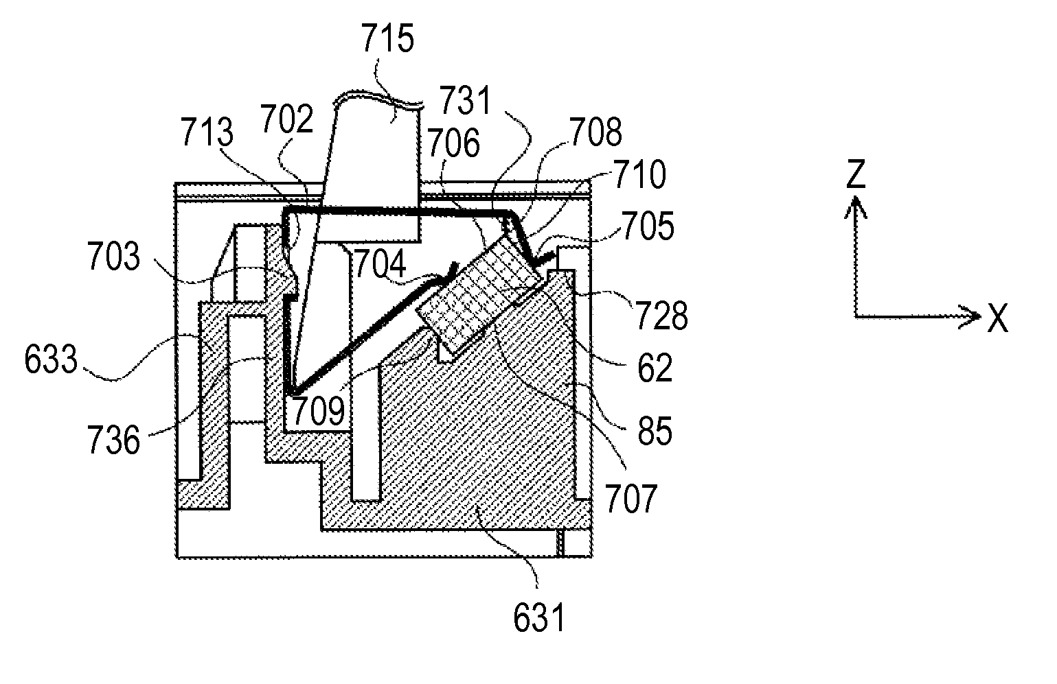
[0009]The present invention has been made in view of the above-mentioned circumstances, and therefore provides a light scanning apparatus and an image forming apparatus which suppresses the occurrence of chipping and cracking of an optical member in the process from the start of attaching an elastic member until achieving a state in which the elastic member is attached in a predetermined position.

Problems solved by technology

However, there are the following problems with this structure.
In addition, in the structure of FIG. 9A, the following problem arises at the time of attaching the leaf spring.

Method used


Image

  • Light scanning apparatus and image forming apparatus
  • Light scanning apparatus and image forming apparatus
  • Light scanning apparatus and image forming apparatus

Examples


Embodiment Construction

[0027]The embodiments of the present invention will hereinafter be described in detail with reference to the accompanying drawings.

[0028]Structure of Image Forming Apparatus

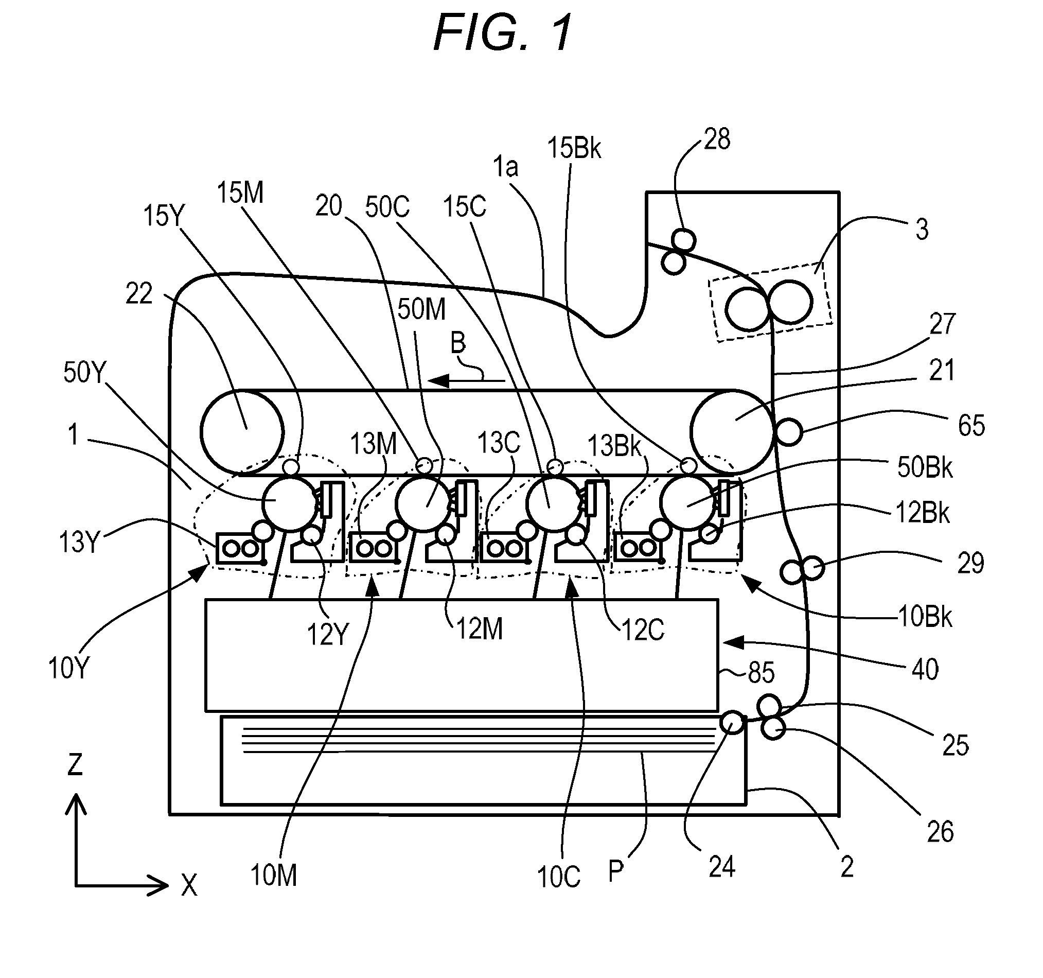
[0029]The structure of an image forming apparatus according to the embodiment will be described. FIG. 1 is a cross-sectional view illustrating the entire structure of a tandem-type color laser beam printer according to the embodiment. The laser beam printer (hereinafter simply referred to as a printer) includes four image forming engines (image forming portions) 10Y, 10M, 10C, and 10Bk (indicated by the dashed lines) configured to form toner images of yellow (Y), magenta (M), cyan (C), and black (Bk), respectively. Further, the printer includes an intermediate transfer belt 20 onto which the toner image is transferred from each of the image forming engines 10Y, 10M, 10C, and 10Bk. The printer transfers the toner images transferred in multiple layers on the intermediate transfer belt 20 onto a recording sheet P as...


PUM


Abstract

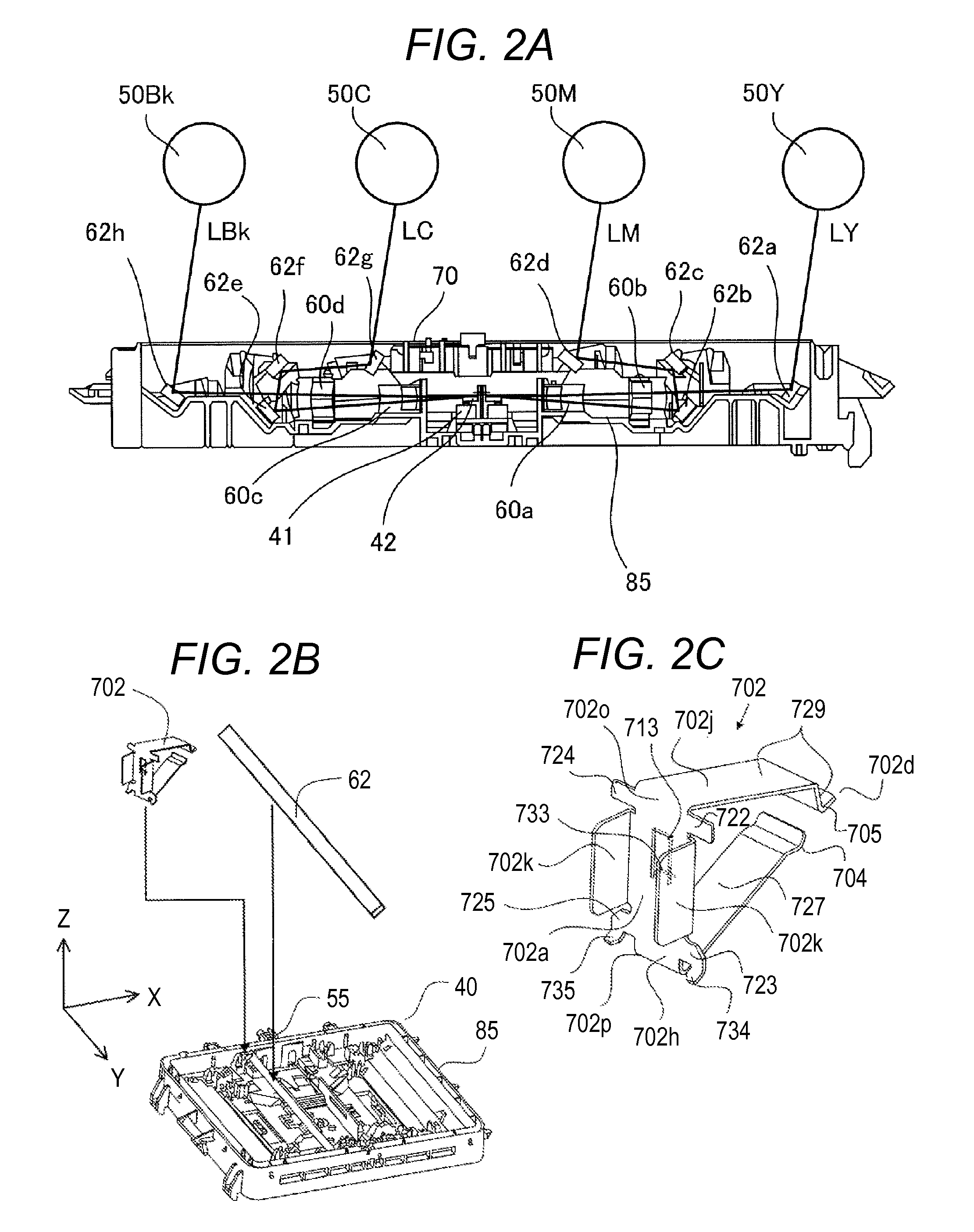
A light scanning apparatus, including: a light source; a deflector configured to deflect the light beam from the light source to scan a photosensitive member; an optical member configured to guide the light beam; a housing including a housing engaging portion and a supporting portion configured to support the optical member; a leaf spring including a pressing portion and a leaf spring engaging portion; and an abutment portion, wherein, in a process in which the housing engaging portion and the leaf spring engaging portion are moved from a second state in which the leaf spring engaging portion is not engaged with the housing engaging portion to a first state in which the leaf spring engaging portion is engaged with the housing engaging portion, the pressing portion is moved from the abutment portion to the optical member.

Description

BACKGROUND OF THE INVENTION[0001]1. Field of the Invention[0002]The present invention relates to a light scanning apparatus, and an image forming apparatus including the light scanning apparatus.[0003]2. Description of the Related Art[0004]Hitherto, an electrophotographic image forming apparatus includes a light scanning apparatus configured to scan a uniformly charged surface of a photosensitive member (hereinafter referred to as a “photosensitive drum” for convenience) with a light beam modulated in accordance with image information, to form a latent image on the surface of the photosensitive drum. The latent image formed on the photosensitive drum is developed into a toner image with developer (toner). Then, the toner image on the photosensitive drum is transferred and fixed to a recording medium. In this manner, an image is formed on the recording medium.[0005]The light scanning apparatus includes a semiconductor laser (light source), a rotary polygon mirror (deflection member) ...

Claims


Application Information

Patent Timeline
Patent Type & Authority Patents(United States)
IPC IPC(8): G02B26/12G03G15/04
CPCG02B26/125G03G15/0409G03G15/04072G02B7/182
Inventor ISHIDATE, TAKEHIROOTOGURO, YASUAKIKAWANO, JUICHI
Owner CANON KK
Learn More