Camera module

a technology of camera module and camera body, applied in the field of camera module, can solve the problems of black spot or staining of image, defects in image capture, etc., and achieve the effect of reducing image sensor and reducing pollution

Active Publication Date: 2015-11-24
LG INNOTEK CO LTD
View PDF44 Cites 0 Cited by
  • Summary
  • Abstract
  • Description
  • Claims
  • Application Information

AI Technical Summary

Benefits of technology

[0009]Exemplary aspects of the present disclosure are to substantially solve at least the above problems and / or disadvantages and to provide at least the advantages below. Accordingly, an aspect of the present disclosure provides a camera module improved in structure mounting a UV (Ultraviolet) cut filter on a base. Another aspect of the present disclosure provides a camera module having an image sensor reduced in generation of a black spot-oriented defect caused by foreign objects.
[0037]The present disclosure has an advantageous effect in that a dam is formed at an upper surface of an image sensor, and a dust trap is formed at an upper surface of the image sensor at a periphery of the dam to thereby trap more foreign objects dropping from the image sensor, and the image sensor is reduced in being generated with black spot defects caused by the foreign objects.
[0038]The present disclosure has a further advantageous effect in that a dam is formed at an upper surface of an image sensor, whereby the formed dust trap can prevent an active region of the image sensor from being polluted.
[0039]The present disclosure has a still further advantageous effect in that a dust trap can be formed at an upper surface of the image sensor at a periphery of the dam, at a lateral surface of the image sensor and at an upper surface of a substrate to form an increased area of dust trap about the image sensor, whereby most of the foreign objects moving at the upper surface of the image sensor can be trapped and the foreign objects are prevented from dropping to the active region.

Problems solved by technology

However, a camera module includes therein many factors capable of generating foreign objects, and foreign objects may drop on an upper surface of the image sensor to disadvantageously generate a black spot or stain phenomenon, thereby causing defects in the image captured by the camera module, or causing the image appear as a black spot or stain.

Method used


Image

  • Camera module
  • Camera module
  • Camera module

Examples


Embodiment Construction

[0058]Hereinafter, exemplary embodiments of the present disclosure will be described in detail with reference to the accompanying drawings.

[0059]In describing the present disclosure, detailed descriptions of constructions or processes known in the art may be omitted to avoid obscuring appreciation of the invention by a person of ordinary skill in the art with unnecessary detail regarding such known constructions and functions. Accordingly, the meaning of specific terms or words used in the specification and claims should not be limited to the literal or commonly employed sense, but should be construed or may be different in accordance with the intention of a user or an operator and customary usages. Therefore, the definition of the specific terms or words should be based on the contents across the specification.

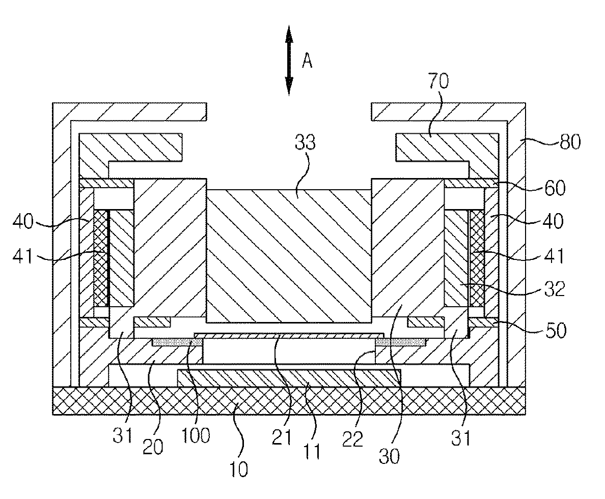
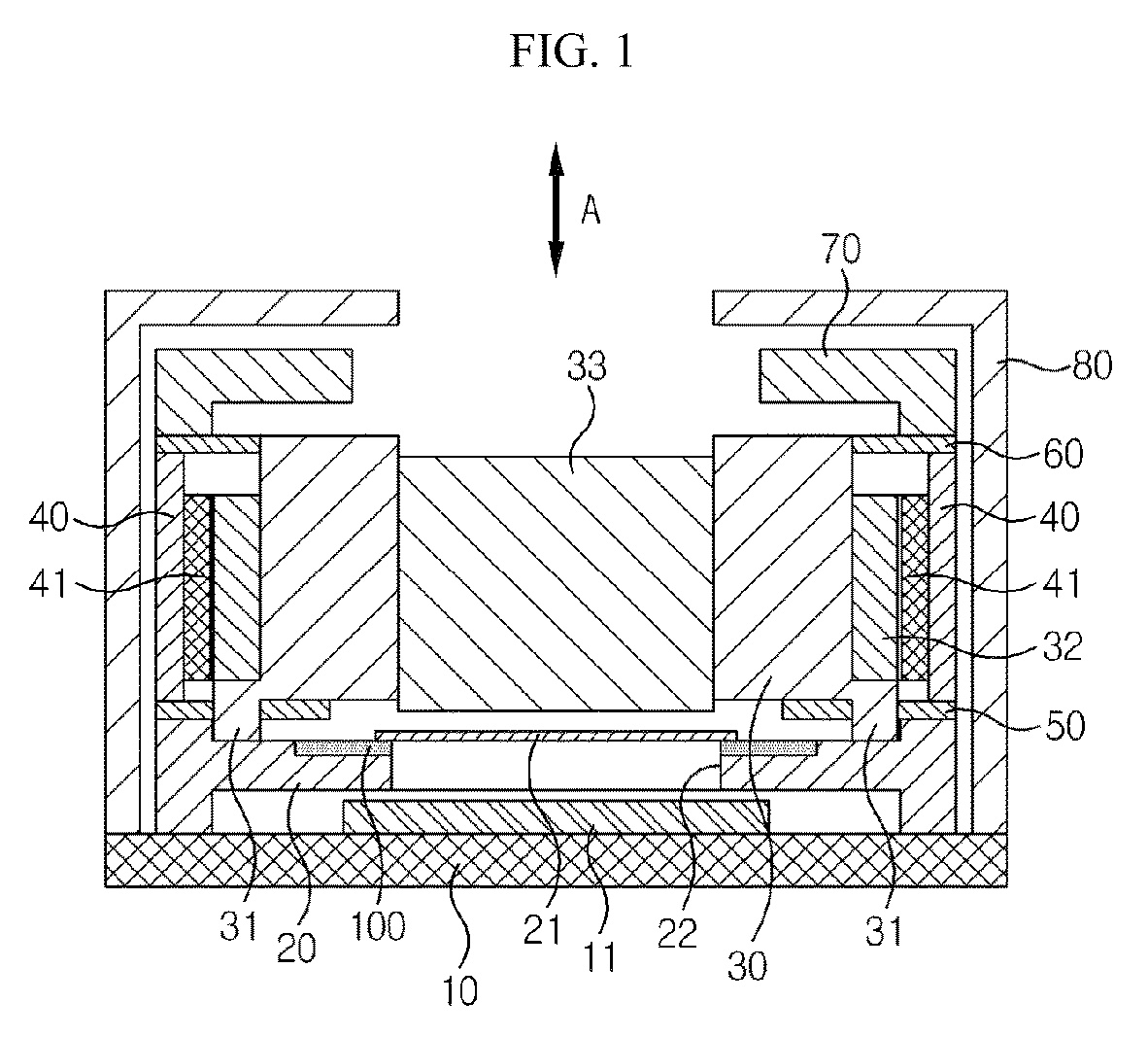
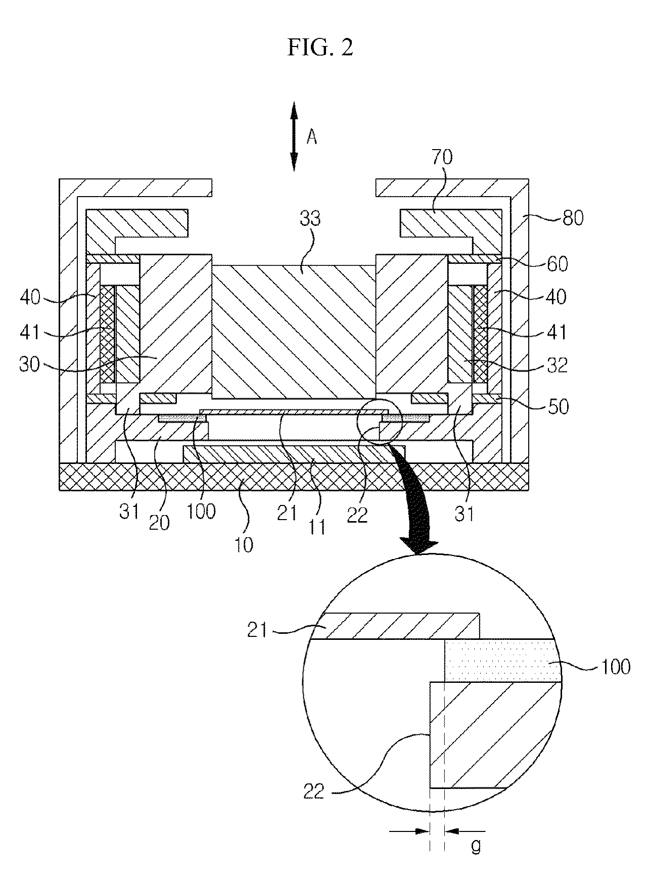
[0060]FIG. 1 is a cross-sectional view illustrating a schematic structure of a camera module according to a first exemplary embodiment of the present disclosure, FIG. 2 is a ...


PUM


Abstract

Exemplary embodiments of a camera module are proposed, the camera module including a PCB (Printed Circuit Board) mounted with an image sensor, a base installed at an upper surface of the PCB and formed with a window at a position corresponding to that of the image sensor, an IRCF (Infrared Cut Filter) installed at an upper surface of the base, and an adhesive member fixing the IRCF to the base.

Description

[0001]Pursuant to 35 U.S.C. §119 (a), this application claims the benefit of earlier filing dates and rights of priorities to Korean Patent Application Nos. 10-2011-0123090, filed on Nov. 23, 2011, 10-2011-0125610, filed on Nov. 29, 2011, and 10-2011-0125612, filed on Nov. 29, 2011, the contents of which are hereby incorporated by reference in their entirety.BACKGROUND OF THE DISCLOSURE[0002]1. Field of the Disclosure[0003]The teachings in accordance with exemplary embodiments of the present disclosure generally relate generally to a camera module.[0004]2. Discussion of the Related Art[0005]This section provides background information related to the present disclosure which is not necessarily prior art.[0006]Generally, an auto focusing adjustment of a camera module is realized by lens control using a VCM (Voice Coil Motor). A camera module formed with a VCM performs a reciprocating operation of a bobbin relative to an image sensor in response to an interaction between a coil wound o...

Claims


Application Information

Patent Timeline
Patent Type & Authority Patents(United States)
IPC IPC(8): H04N5/225
CPCH04N5/2253H04N5/2257H04N2201/03191H04N23/52H04N23/54H04N23/57G02B5/208G02B7/025G02B7/09G02B27/0006
Inventor OH, HYUN AHJEONG, YOUN BAEKLEE, SE JIN
Owner LG INNOTEK CO LTD
Why Eureka
Try Eureka