Liquid jet head, method of manufacturing liquid jet head, and liquid jet apparatus

a liquid jet head and manufacturing method technology, applied in the direction of printing, inking apparatus, etc., can solve the problems of increasing manufacturing man-hours, not being able to eject liquid from the nozzle hole, and not being able to apply drive voltage to the drive electrode, so as to increase manufacturing man-hours and reduce costs.

Active Publication Date: 2015-12-01
SII PRINTEK
View PDF10 Cites 0 Cited by
  • Summary
  • Abstract
  • Description
  • Claims
  • Application Information

AI Technical Summary

Benefits of technology

[0009]However, in a conventional liquid jet head, since corners between side faces and top surfaces of two partition walls which form a non-ejection channel are cut to form chamfered portions, it is necessary to individually perform cutting on a plurality of non-ejection channels, and manufacturing man-hours therefore increase. Therefore, there is still room for improvement in cost reduction by reducing the manufacturing man-hours.
[0010]In view of the above, the present invention is directed to provide a low-cost liquid jet head that is capable of preventing electrical short circuit between wiring on an external substrate and an electrode on an actuator substrate, a method of manufacturing the liquid jet head, and a liquid jet apparatus provided with the liquid jet head.

Problems solved by technology

In this case, when the common wiring electrode and the individual electrodes come into contact with each other and short circuit therebetween thereby occurs, it is not possible to apply drive voltage to the drive electrodes.
As a result, it is not possible to eject liquid from the nozzle holes.
However, in a conventional liquid jet head, since corners between side faces and top surfaces of two partition walls which form a non-ejection channel are cut to form chamfered portions, it is necessary to individually perform cutting on a plurality of non-ejection channels, and manufacturing man-hours therefore increase.

Method used


Image

  • Liquid jet head, method of manufacturing liquid jet head, and liquid jet apparatus
  • Liquid jet head, method of manufacturing liquid jet head, and liquid jet apparatus
  • Liquid jet head, method of manufacturing liquid jet head, and liquid jet apparatus

Examples


first embodiment

Modified Example of First Embodiment

[0113]FIG. 8 is a perspective view of an actuator substrate 2 according to a modified example of the first embodiment.

[0114]Next, the actuator substrate 2 according to the modified example of the first embodiment will be described. Hereinbelow, a description of the same components as those of the first embodiment will be omitted, and only differences from the first embodiment will not be repeated.

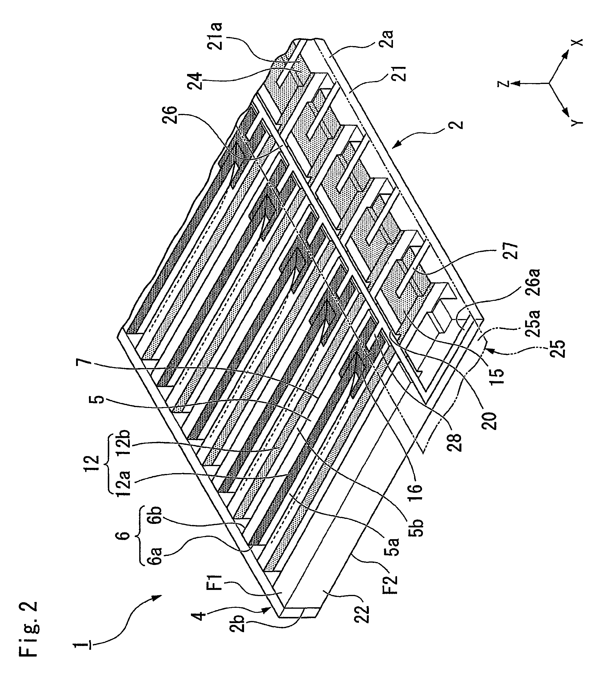
[0115]In the actuator substrate 2 of the first embodiment, the individual electrode pads 15 are formed across respective adjacent ones of the non-ejection channels 6b on the first principal face F1 of the actuator substrate 2 (see FIG. 2).

[0116]On the other hand, as illustrate in FIG. 8, in the actuator substrate 2 according to the modified example of the first embodiment, individual electrode pads 15 are formed between respective adjacent ones of the non-ejection channels 6b on the first principal face F1 of the actuator substrate 2. In this manner, a fo...

second embodiment

Effect of Second Embodiment

[0149]According to the second embodiment, the shallow grooves 23 are formed from the +X side ends of the ejection channels 6a toward the +X side end face 2a of the actuator substrate 2. Therefore, when forming the ejection channels 6a, for example, by cutting, the shallow grooves 23 can be formed merely by changing the depth of cutting. Therefore, it is possible to easily form the shallow grooves 23 within the channel forming step S16. Further, the groove 20 is formed so as to intersect the shallow grooves 23. Therefore, the common electrode pads 16 and the individual electrode pads 15 can be easily formed by forming the groove 20 so as to interest the shallow grooves 23, for example, by cutting after forming the film of the electrode material 56 inside the shallow grooves 23 to thereby divide the film of the electrode material 56 formed inside the shallow grooves 23 by the groove 20. In this manner, since the common electrode pads 16 and the individual el...


PUM

PropertyMeasurementUnit
liquidaaaaaaaaaa
widthaaaaaaaaaa
flexibleaaaaaaaaaa

Abstract

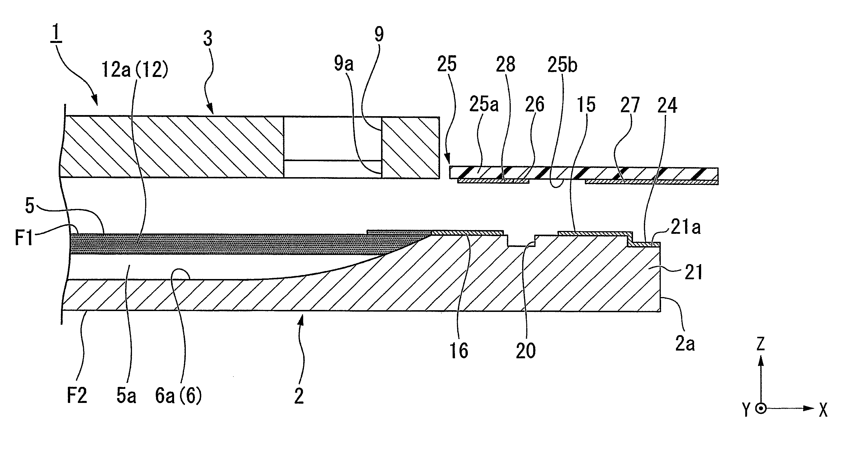
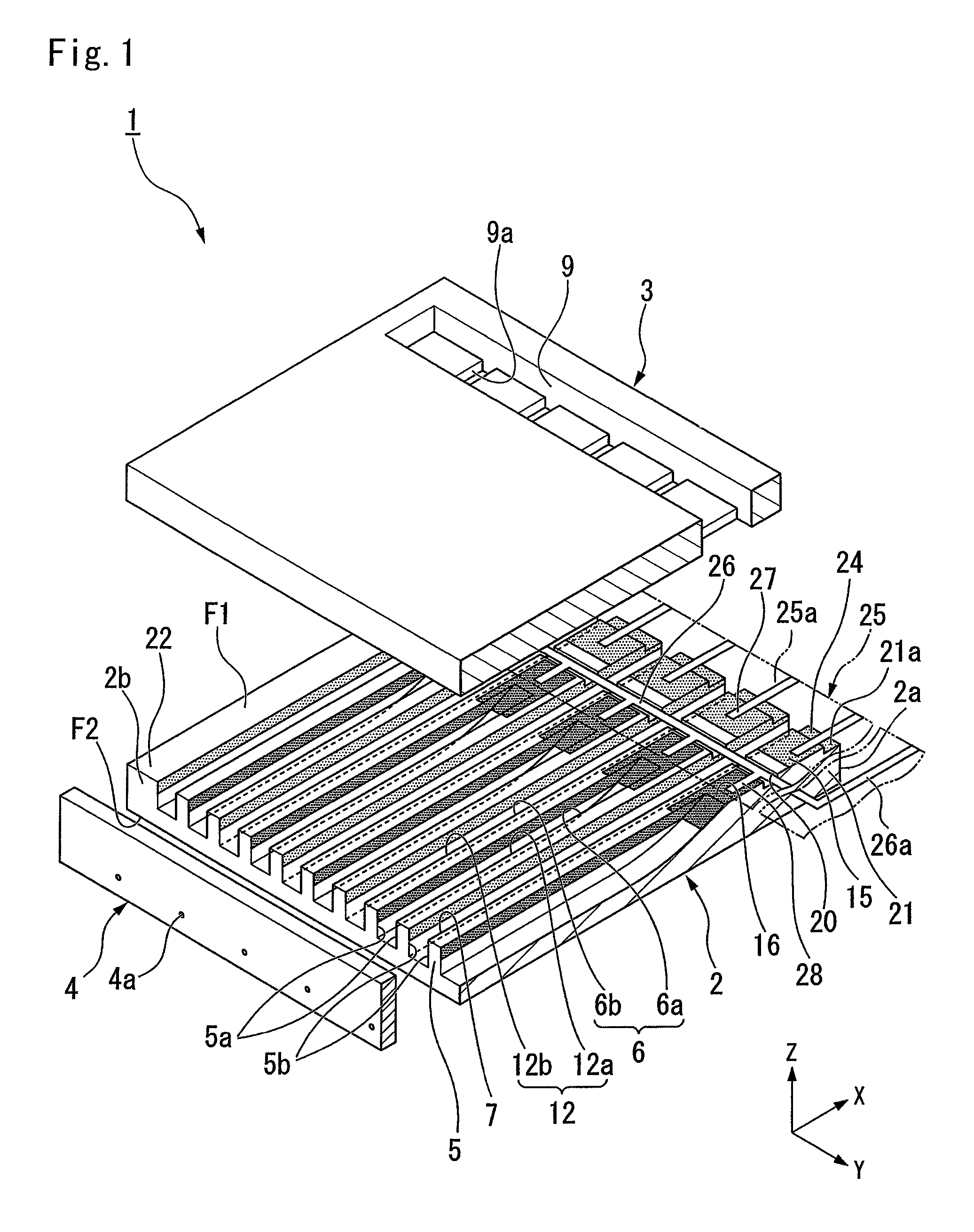
A liquid jet head includes an actuator substrate having a principal surface on which ejection channels and non-ejection channels are formed, common electrodes formed on side surfaces of the ejection channels, individual electrodes formed on side surfaces of the non-ejection channels, individual electrode pads for connection to the individual electrodes, and common electrode pads for connection to the common electrodes. A groove is formed on the principal surface of the actuator substrate for isolating the individual electrode pads and the common electrode pads from one another. An external substrate has individual electrode terminals and common electrode terminals for connection to the individual electrode pads and common electrode pads, respectively. A connection wiring that connects the common electrode terminals to each other is formed along the groove to prevent an electrical short circuit between the connection wiring and the individual electrodes.

Description

BACKGROUND[0001]1. Technical Field[0002]The present invention relates to a liquid jet head, a method of manufacturing the liquid jet head, and a liquid jet apparatus.[0003]2. Related Art[0004]Conventionally, as an apparatus that jets liquid such as ink onto a recording medium such as a recording paper to record a character or a figure thereon, a liquid jet recording apparatus that includes a so-called ink jet type liquid jet head which jets liquid from a plurality of nozzle holes toward a recording medium has been known.[0005]There is known a liquid jet head that includes an actuator substrate and a flexible substrate. The actuator substrate includes ejection channels which are elongated in a direction from the front end to the rear end of the surface of the substrate, separated from each other by partition walls, and arrayed in a direction that is perpendicular to the elongated direction, drive electrodes which are formed on side faces of the partition walls and include common elec...

Claims


Application Information

Patent Timeline
Patent Type & Authority Patents(United States)
IPC IPC(8): B41J2/015B41J2/16B41J2/14
CPCB41J2/1631B41J2/14209Y10T29/42B41J2202/18B41J2002/14491B41J2/1609B41J2202/10
Inventor HARAJIRI, TOSHIHIKOKUBOTA, YUZURUHORIGUCHI, SATOSHI
Owner SII PRINTEK
Why Eureka
Try Eureka