Cable connector assembly having simple wiring arrangement between two end connectors

a technology of connector assembly and end connector, which is applied in the direction of coupling device connection, two-part coupling device, electrical apparatus, etc., can solve the problem of complicated manufacturing process of soldering the crossed control wir

Active Publication Date: 2015-12-01
HON HAI PRECISION IND CO LTD
View PDF98 Cites 54 Cited by
  • Summary
  • Abstract
  • Description
  • Claims
  • Application Information

AI Technical Summary

Benefits of technology

[0008]An object of the present invention is to provide a cable connector assembly easy for soldering cable wires thereof.
[0010]According to the present invention, the connector assembly avoids the crossed soldering to simplify the manufacture procedure. It is more convenient because of using a flat cable instead of the core wires which are soldered separately.

Problems solved by technology

The manufacturing process of soldering the crossed control wires is complicated.

Method used


Image

  • Cable connector assembly having simple wiring arrangement between two end connectors
  • Cable connector assembly having simple wiring arrangement between two end connectors
  • Cable connector assembly having simple wiring arrangement between two end connectors

Examples


Embodiment Construction

[0020]Reference will now be made in detail to a preferred embodiment of the present invention.

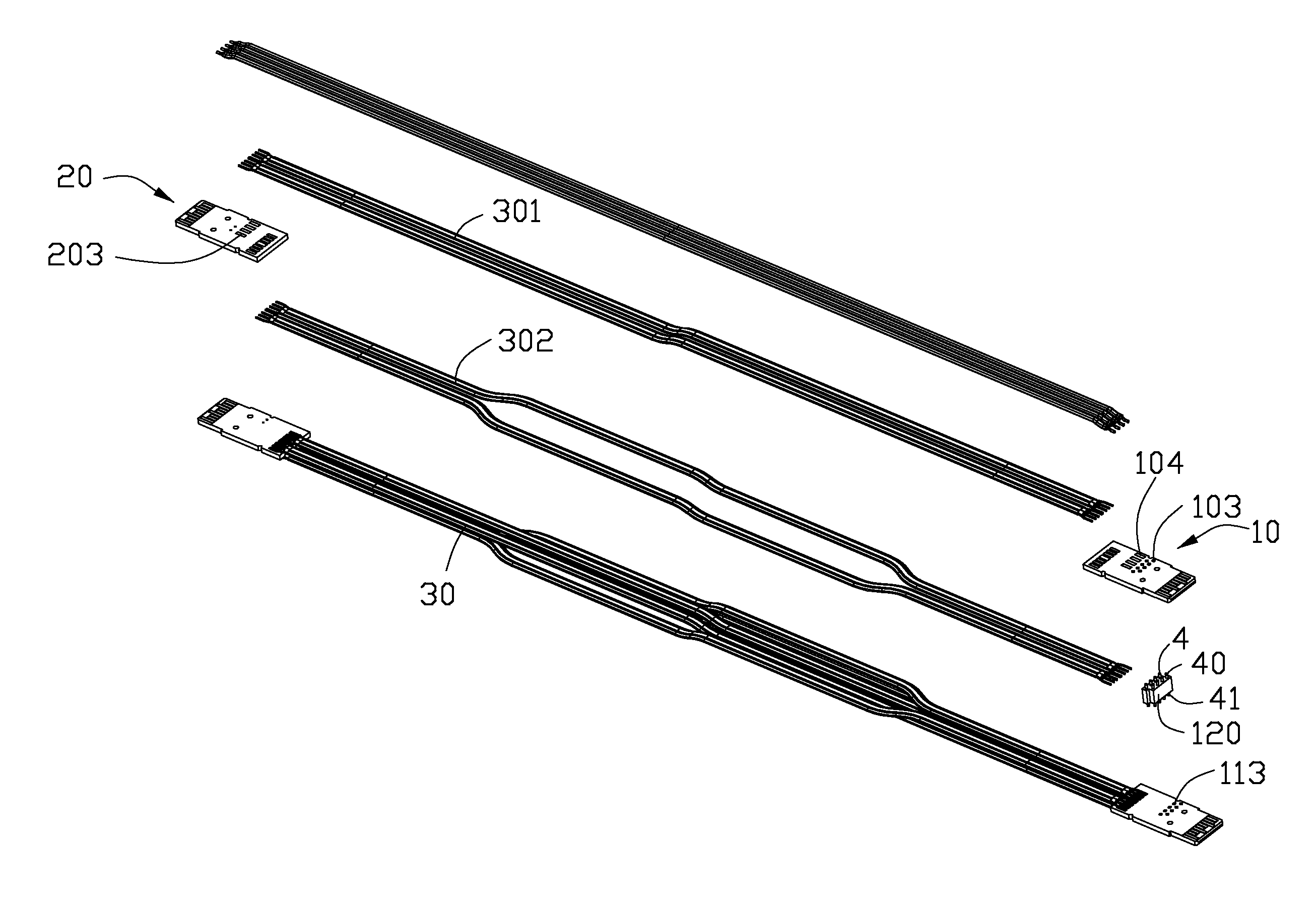
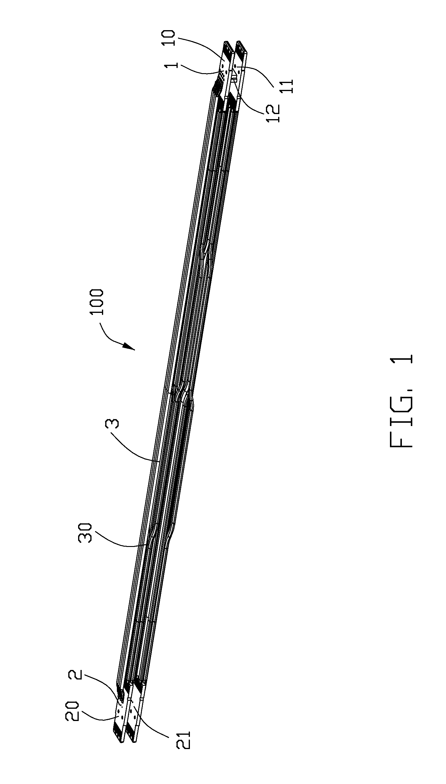
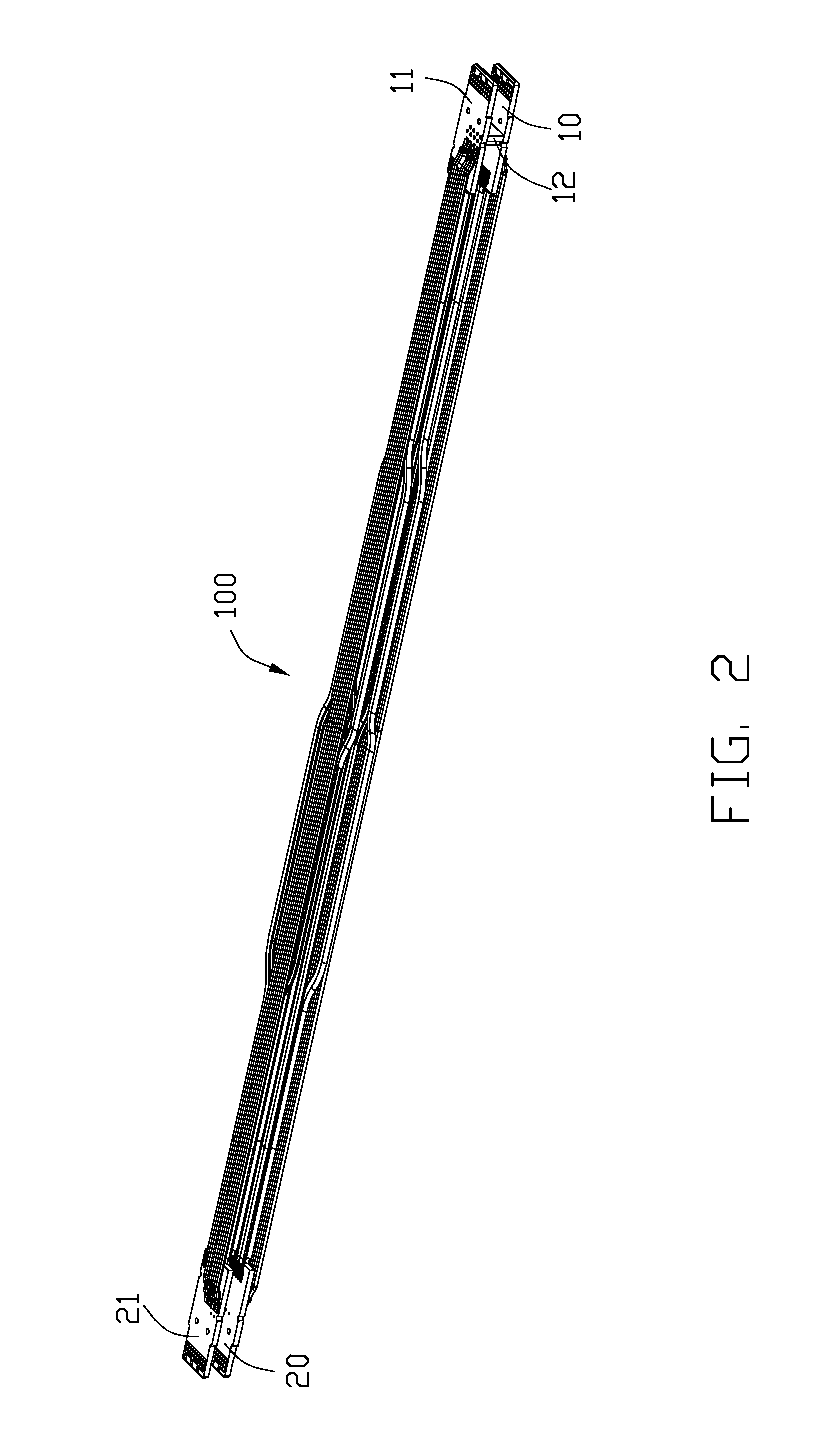
[0021]Referring to FIG. 1, a cable connector assembly 100 comprises a first connector 1, a second connector 2, and a cable 3 connecting the first connector 1 to the second connector 2. Understandably, one of the first connector 1 and the second connector could be for an input purpose and the other for the output purpose, or in a reciprocal manner either wholly or partially. Anyhow, for easy illustration of the whole structural relation among the detailed components, the first connector 1 and the second connector 2 may be named respectively as the input connector and the output connector rather than using the order numerals.

[0022]Referring to FIGS. 1 to 3, the first connector 1 comprises a first printed circuit board 10, a second printed circuit board 11 spaced apart from and disposed below the first printed circuit board 10, and a connecting member 12 electrically connecting the first and s...


PUM


Abstract

A cable connector assembly includes a first connector, a second connector, and a cable connecting the first connector to the second connector. The first connector includes a first printed circuit board, a second printed circuit board, and a connecting member between the first and the second printed circuit boards. The second connector includes a third printed circuit board and a fourth printed circuit board. The cable includes a number of signal wires for transmitting data signals and a number of control wires for transmitting control signals. The control wires includes a number of first control wires connecting the first and the third printed circuit boards and a number of second control wires connecting the second and the fourth printed circuit boards.

Description

BACKGROUND OF THE INVENTION[0001]1. Field of the Invention[0002]The present invention relates to a connector assembly, and more particularly to a signal transmitting structure of the connector assembly.[0003]2. Description of Related Arts[0004]It is known for a SAS (Serial Attached SCSI) External cable assembly to have a wiring arrangement that data signals are transmitted between a first cable end connector and a second cable end connector. In particular, the first connector comprises a first (upper) printed circuit board (PCB) and a second (lower) PCB, and the second connector comprises a third (upper) PCB and a fourth (lower) PCB. Data signals are transmitted straightforwardly between the second and the fourth PCBs and between the first and the third PCBs. Therefore, cable wires are soldered accordingly without cross-soldering, e.g., cable wires soldered to the second PCB of the first connector and to both the fourth and the third PCBs of the second connector.[0005]The specificat...

Claims


Application Information

Patent Timeline
Patent Type & Authority Patents(United States)
IPC IPC(8): H01R12/73H01R24/64H01R12/62
CPCH01R12/73H01R24/64H01R12/62
Inventor YU, LEWANG, CHIEN-CHIUNG
Owner HON HAI PRECISION IND CO LTD
Why Eureka
Try Eureka