

Microwave system and method
a technology of microwave and microwave oven, applied in microwave heating, electrical/magnetic/electromagnetic heating, electrical apparatus, etc., can solve problems such as uneven heating, failure of previous designs, and failure of attempts so far to achieve high efficiency
- Summary
- Abstract
- Description
- Claims
- Application Information
AI Technical Summary
Benefits of technology
Problems solved by technology
Method used
Image

Examples
Embodiment Construction
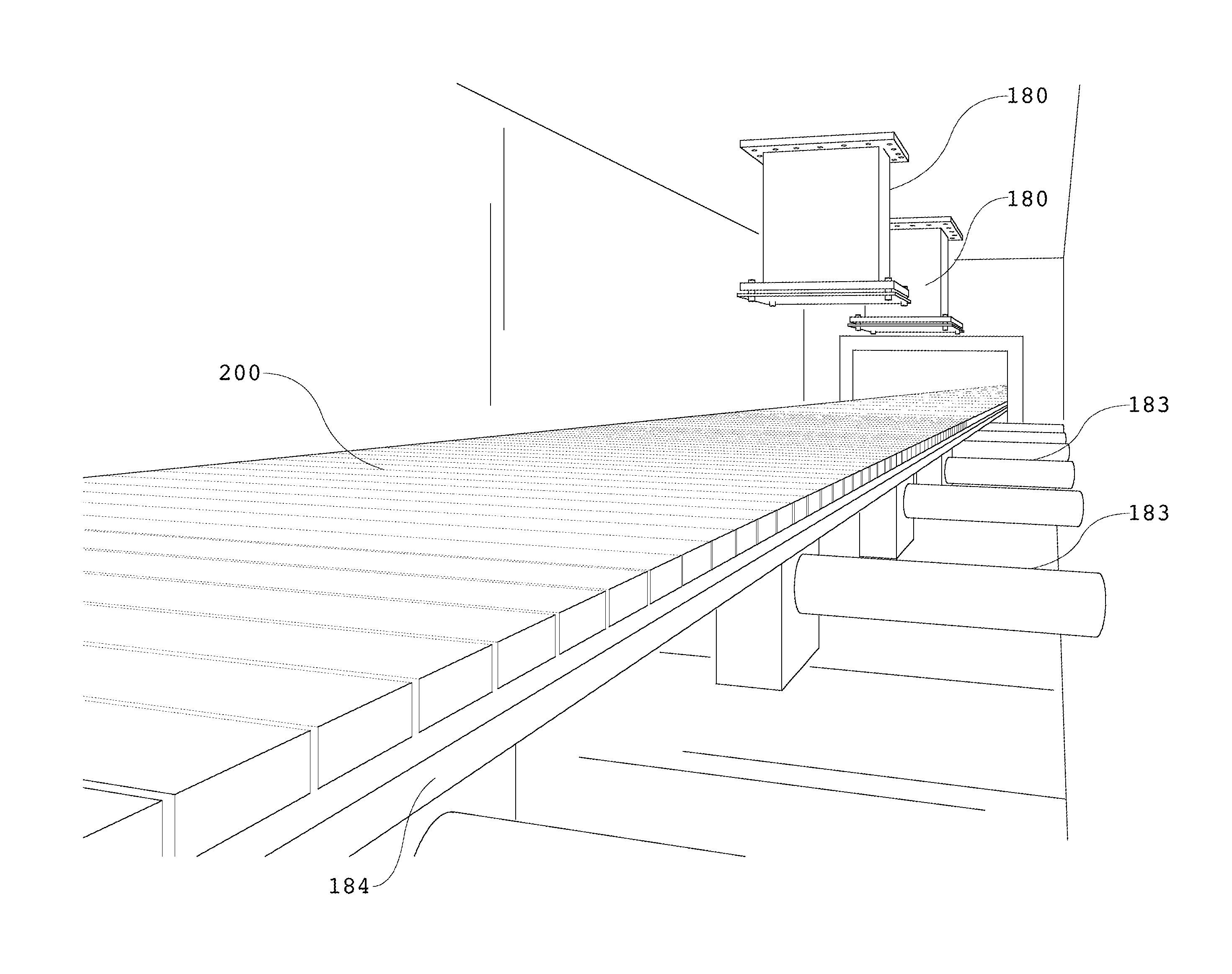
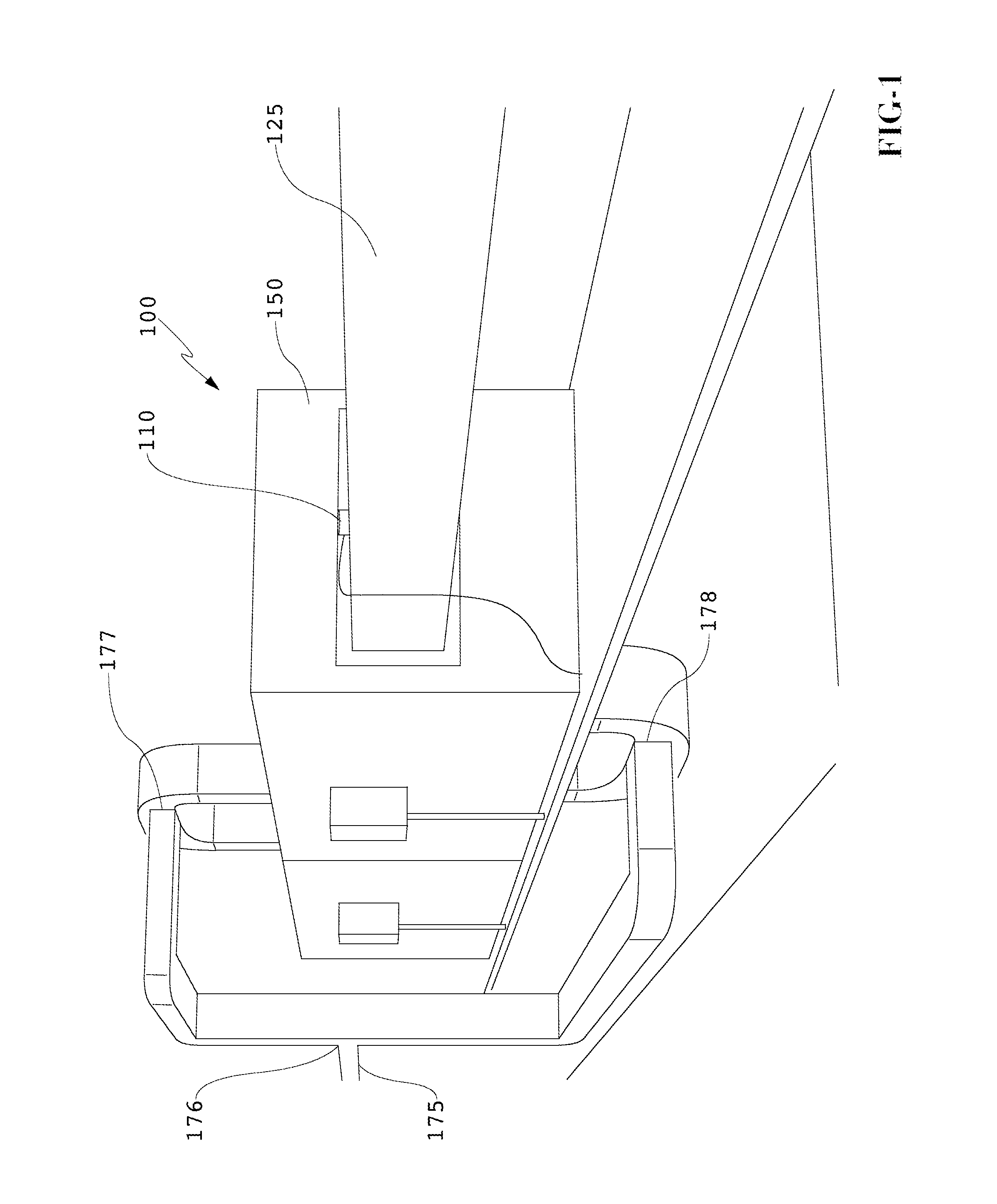
[0006]An exemplary embodiment uses a microwave oven which applies microwave energy directly to the products in a uniform, controlled, and repeatable manner. The design of an exemplary oven allows all of the microwave energy to be absorbed by the food and does not allow microwave energy to be absorbed by containers or the interior of the oven, or escape from the oven itself. Thus, the ovens operate at a very high efficiency. The interior of the oven cavities may be completely flat and square so that no welds or protrusions can attract or absorb microwave energy or disrupt the flow of energy waves within the oven.
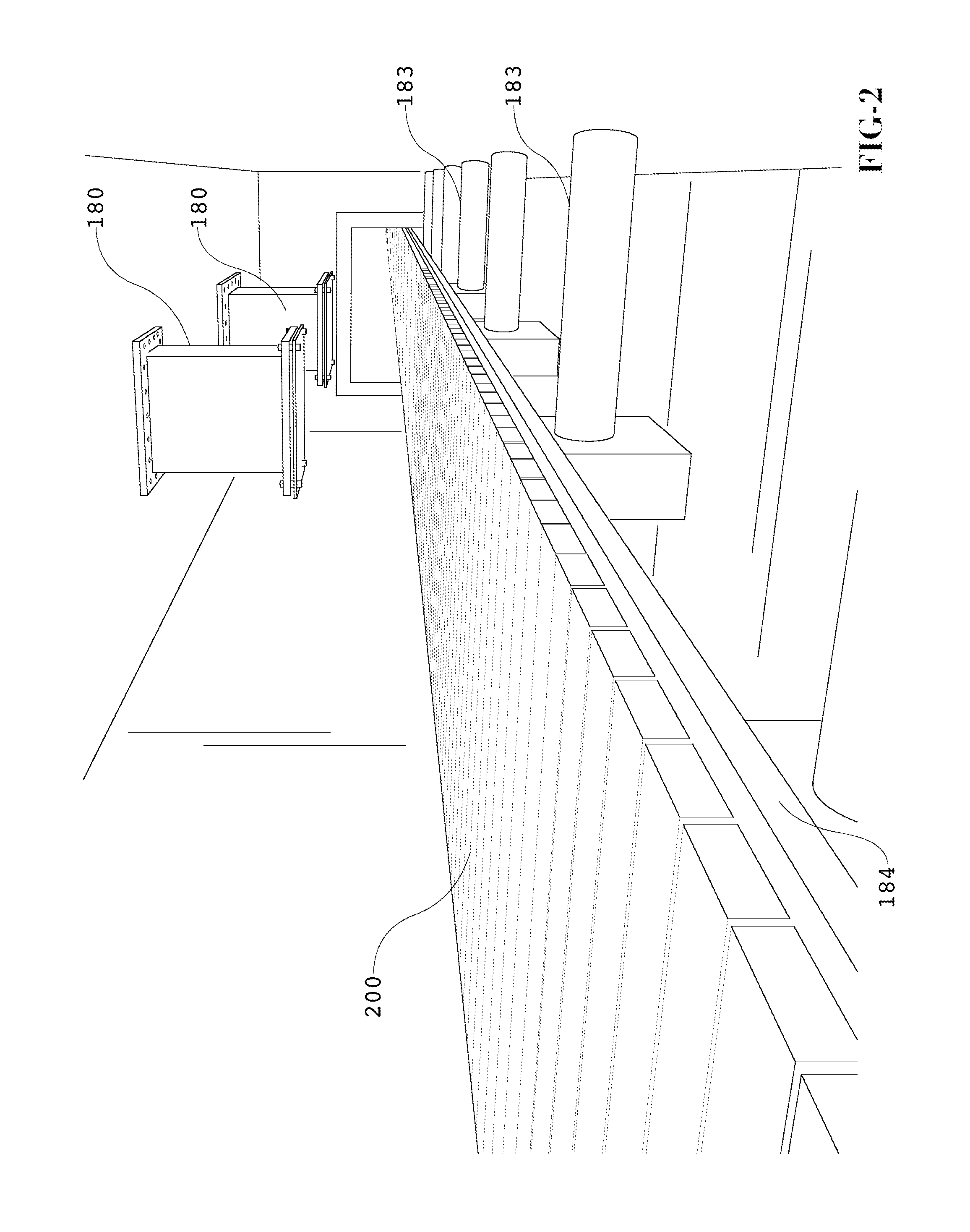
[0007]An exemplary system and method may use a plurality of exemplary ovens in series with relaxation sections in between each oven. A conveyer may be designed for each oven so that the speed at which the products move through each oven can be precisely controlled and matched with the microwave energy input that each oven is providing. An exemplary system may also use trays t...
PUM
| Property | Measurement | Unit |
|---|---|---|
| speed | aaaaa | aaaaa |
| microwave energy | aaaaa | aaaaa |
| width | aaaaa | aaaaa |
Abstract
Description
Claims
Application Information