Nerve stimulator system

a stimulator and energy technology, applied in the field of energy impulse delivery, can solve the problems of mechanical stress and the resulting chronic tissue response, energy source would also and energy source would likely have the disadvantage of having to be placed clos

Active Publication Date: 2015-12-08
ELECTROCORE
View PDF60 Cites 86 Cited by
  • Summary
  • Abstract
  • Description
  • Claims
  • Application Information

AI Technical Summary

Benefits of technology

[0026]In one aspect of the invention, a stimulation device comprises one or more electrodes and a pulse generator. The pulse generator is configured to generate an electrical impulse having a fixed amplitude (either fixed voltage or fixed current) and a variable duration. The electrical impulse is applied through the electrodes to excitable tissue, such as nerve or nerve ganglions, to modulate that tissue. In a preferred embodiment, the duration of the electrical impulse is varied by varying a number of fixed-duration, fixed-amplitude pulses that are applied within each electrical impulse. Varying the number of these fixed-amplitude pulses allows the stimulation device to apply an electrical impulse that will cause the nerve to reach its threshold potential without varying the amplitude of the electrical impulse.
[0027]The stimulator circuit is novel in that it removes one or more elements from conventional stimulators, without sacrificing performance. In particular, the present invention removes from conventional designs the ability of the stimulator to vary the amplitude of the stimulation pulses. Unexpectedly, one can get substantially the same stimulatory effect as that provided by conventional stimulators, by keeping waveform parameters fixed, particularly the amplitude of the electrical impulse, but by then controlling the number and timing of pulses that the nerve experiences, in order to achieve the same physiologically desirable level of nerve stimulation. In essence, this invention uses an adjustable number of fixed voltage (or fixed current) pulses with fixed duration to elicit desired changes in nerve response. These fixed voltage pulses create one long continuous pulse to the nerve to ensure that sufficient energy is delivered to the nerve to cause the nerve to reach its action potential and fire. Thus, the present invention reaches the threshold energy level for a nerve to fire by adjusting the duration of the pulse received by the nerve, rather than adjusting the amplitude of the pulse.
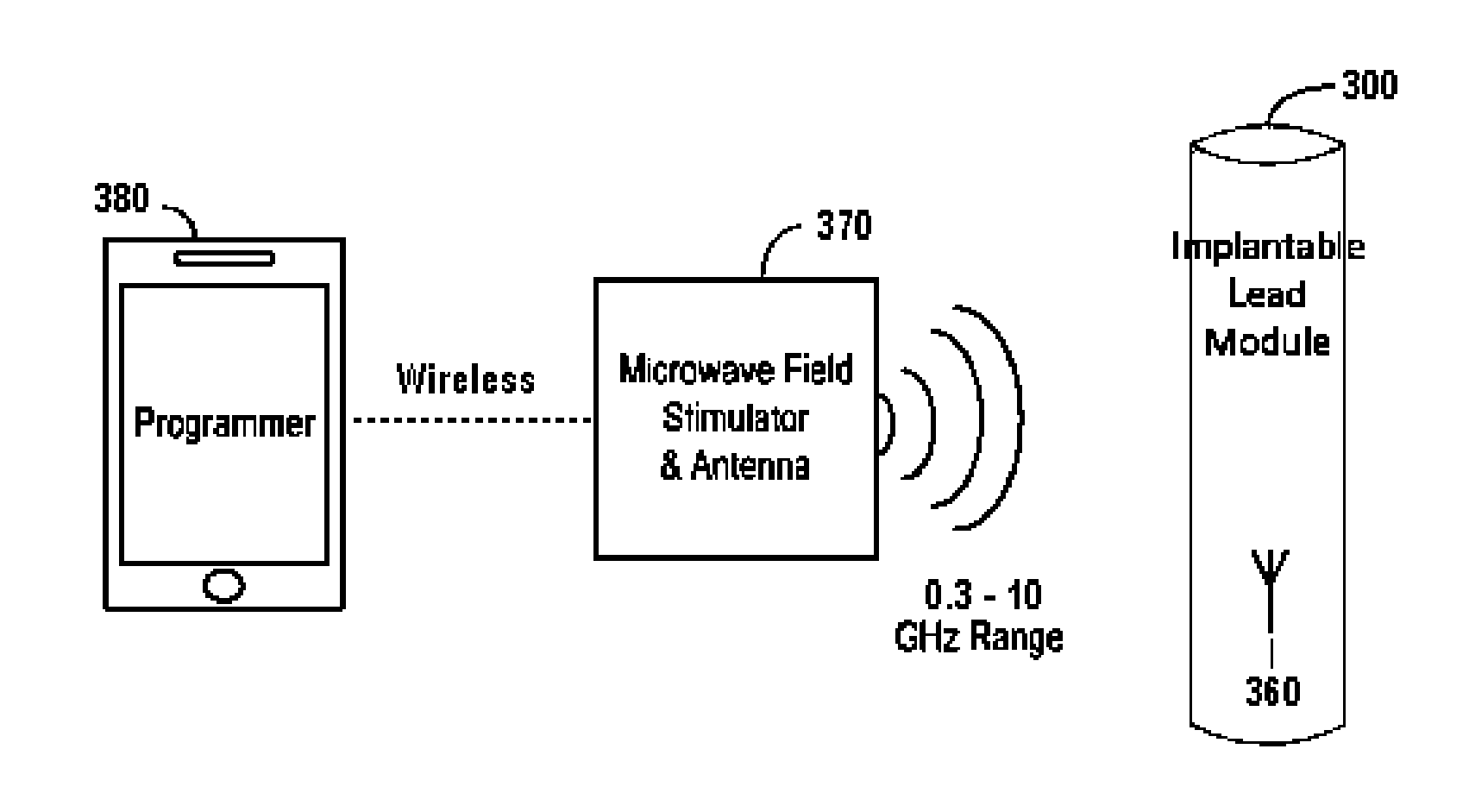
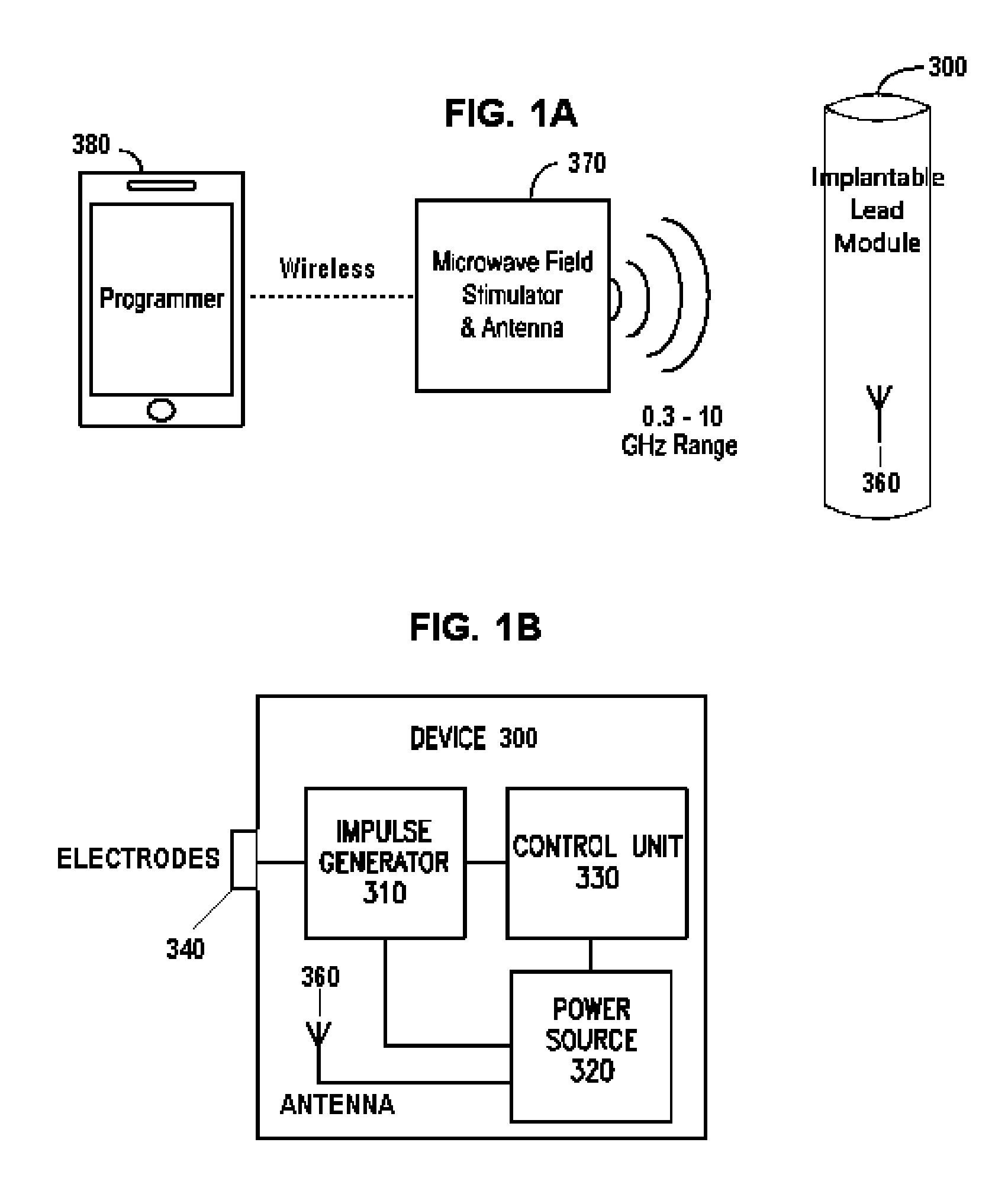
[0030]The present invention provides an implanted peripheral nerve stimulator, such as a vagus nerve stimulator, that can be powered using approximately plane wave or far-field electromagnetic waves with frequencies in the range of 300 MHz to 10 GHz so that the antenna transmitting energy for the stimulator's electrodes does not have to be placed in close proximity to the implanted stimulator in order for the stimulator to receive the energy. In addition, the stimulation device has relatively simple circuitry so as to consume a small amount of power, and also so that the external transmitter can be a relatively weak power source (either inherently or because it is positioned at some distance from the implanted stimulator). In particular, the present invention is advantageous for vagus nerve stimulation because the stimulation device can be implanted with minimally invasive methods, For example, the stimulation device may be implanted through a percutaneous penetration in the neck.
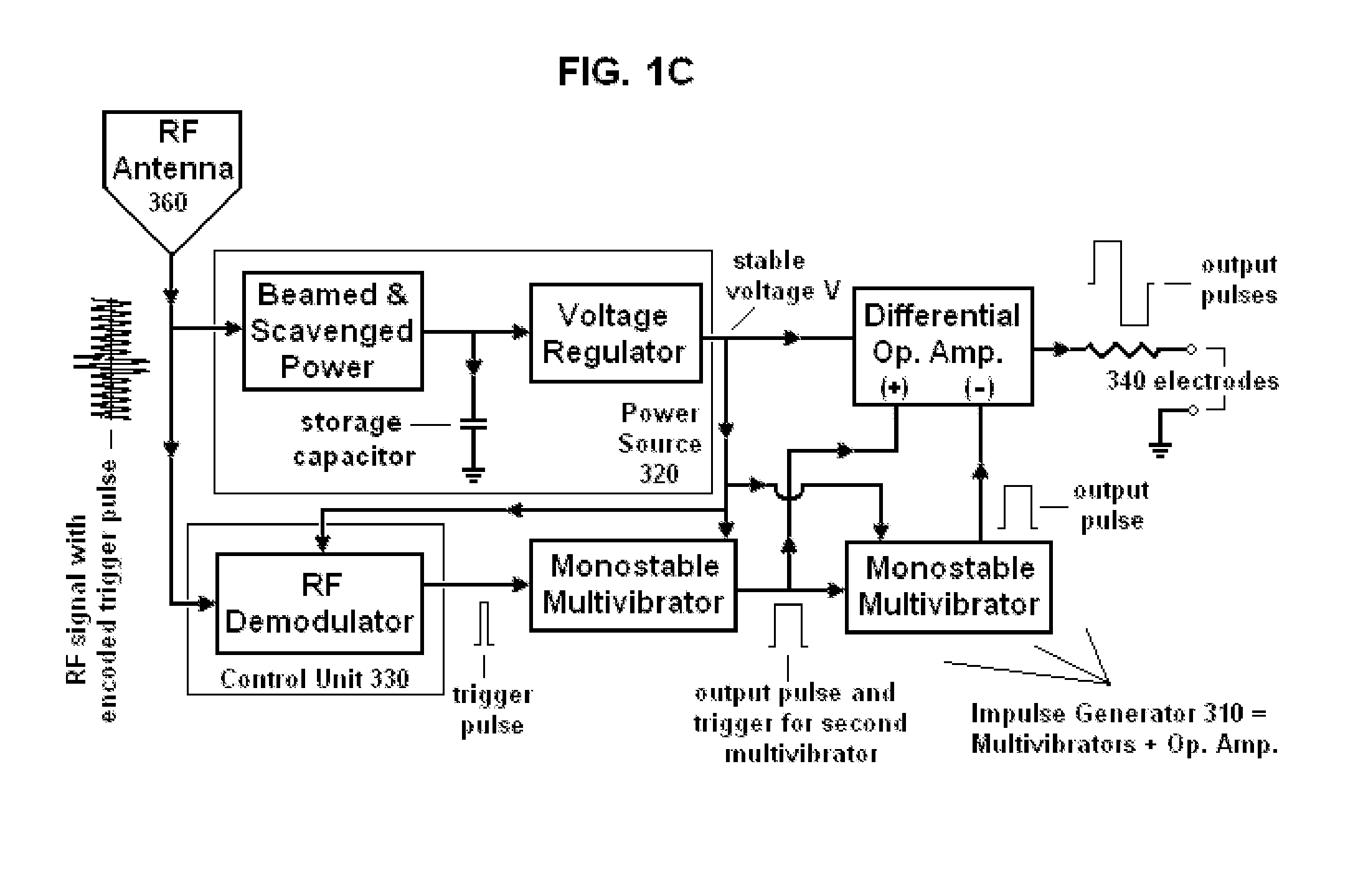
[0032]In another aspect of the invention, the stimulator circuit comprises either a battery or a storage device, such as a capacitor, for storing energy or charge and then delivering that charge to the circuit to enable the circuit to generate the electrical impulses and deliver those impulses to the electrodes. The energy for the storage device is preferably wirelessly transmitted to the stimulator circuit through a carrier signal from the external controller. In the preferred embodiments, the energy is delivered to the energy storage device between electrical impulses. Thus, the energy is not being delivered in “real-time”, but during the periods when the pulse is not being delivered to the nerve or during the refractory period of the nerve. For example, a typical electrical impulse may be ON for about 200 uS and then OFF for about 39,000 uS. The energy is delivered during this longer OFF time, which enables the system to use a much smaller signal from the external generator. The external generator delivers the carrier signal over the OFF period to charge the energy storage device, which then releases this energy or charge to the remainder of the circuit to deliver the electrical impulse during the 200 uS ON time. This reduces the strength of the signal required to deliver the electrical energy to the storage device within the stimulator circuit because there is a longer period of time to deliver the energy. In addition, it enhances the safety of the device because it reduces the risk that uncontrolled environmental RF energy will create an electrical connection between the nerve and the charged energy.
[0034]The electrical impulse is sufficient to modulate a selected nerve (e.g., vagus or one of its branches) at or near the target region to treat a condition or symptom of the patient. The stimulator is configured to induce a peak pulse voltage sufficient to produce an electric field in the vicinity of the nerve, to cause the nerve to depolarize and reach a threshold for action potential propagation. By way of example, the threshold electric field for stimulation of the nerve may be about 8 V / m at 1000 Hz. For example, the device may produce an electric field within the patient of about 10 to 600 V / m (preferably less than 100 V / m) and / or an electrical field gradient of greater than 2 V / m / mm. Electric fields that are produced at the vagus nerve are generally sufficient to excite all myelinated A and B fibers, but not necessarily the unmyelinated C fibers. However, by using a suitable amplitude of stimulation, excitation of A-delta and B fibers may also be avoided.
[0036]A system for implanting the stimulator preferably includes an introducer for creating percutaneous access to the target region. The introducer may include an access device such as a finder needle for creating percutaneous access through a skin surface of the patient's neck, and a cannula having an inner lumen for passage of the stimulator there through. The access device, e.g. finder needle, is introduced through the patient's skin surface in the neck and advanced to a target location, ordinarily near a vagus nerve. The target location may be within, directly adjacent to, or in contact with the carotid sheath, or it may be in close proximity with (e.g., within 1-5 mm) of the carotid sheath. The preferred target location, as well as the preferred path that the finder needle takes to that location, will depend on several factors. They include the length of the stimulator and the number of its electrodes, whether the stimulator's electrodes should produce an electric field that is intended to have particular directionality, whether deployable anchoring attachments will be used to secure the stimulator to particular surrounding tissue, as well as consideration of the electrical waveforms that may be used to preferentially stimulate the vagus nerve (including the maximum strength or amplitude of the stimulus), the likelihood that the other structures will not be damaged during the implantation or eventually co-stimulated, and the ease with which the finder needle may penetrate and actually follow the intended path.

Problems solved by technology

Intrinsic limitations of such coil-based powering systems are that the source oscillating magnetic field must be in close proximity to the implanted pickup coil in order to transfer the energy efficiently (e.g., applied to the patient's skin), and the source and pickup coils have to be optimally oriented with respect to one another.
The stimulators could also be powered by ultrasound or infrared light, in which case the energy source would also likely have the disadvantage of having to be placed close to the implant [ABDO A, Sahin M, Freedman D S, Cevik E, Spuhler P S, Unlu M S. Floating light-activated microelectrical stimulators tested in the rat spinal cord.
However, that potential source is generally limited to situations in which very little power is needed for the device, or the environment contains an unusually high level of ambient electromagnetic energy [E. M. YEATMAN.
In addition to the need to replace a battery, another disadvantage of conventional implanted vagus or peripheral nerve stimulation systems is the mechanical stress and the resulting chronic tissue response caused by the constant movement of tethering electrical cables that are connected to the pulse generator.
Furthermore, the cables may break, and motion of the cables may cause their attached electrode assemblies to migrate or rotate, causing the stimulation system to fail.
Thus, the system described by PERRYMAN et al. would also cause tissue response problems, owing to the movement of the tethering tubing, for the same reason that a tethering electrical cable causes problems.
Nevertheless, there do exist implanted externally-powered nerve stimulation systems that do not contain a tethered lead or tubing after implantation.
Unfortunately, however, those systems are powered externally by inductive coils, not bythe higher frequency approximately plane wave or far-field electromagnetic radiation.
They therefore suffer from the disadvantage that an external coil providing energy to the implanted stimulator must be very close to the implanted pickup coil in order to transfer energy efficiently.
In patients who have difficulty with keloid and painful scar formation, and for those patients who are resistant to a neck scar for cosmetic reasons, conventional vagus nerve stimulator therapy has little appeal, regardless of its effectiveness.
This reduces the strength of the signal required to deliver the electrical energy to the storage device within the stimulator circuit because there is a longer period of time to deliver the energy.

Method used


Image

  • Nerve stimulator system
  • Nerve stimulator system
  • Nerve stimulator system

Examples


Embodiment Construction

[0057]In one or more embodiments of the present invention, electrical energy is applied in a patient to a target region within or around the carotid sheath (also called the carotid neurovascular bundle) to treat a patient's ailment. The invention is particularly useful for applying electrical impulses that ultimately interact with the signals of a vagus nerve, which lies within the carotid sheath, to achieve a therapeutic result. The nerve stimulation may result in benefits to the patient such as: relaxation of the smooth muscle of the bronchia, increase in blood pressure associated with orthostatic hypotension, reduction in blood pressure, treatment of epilepsy, treating ileus conditions, depression, anaphylaxis, obesity, a neurodegenerative disorder such as Alzheimer's disease, migraine and other types of headache, rhinitis, sinusitis, asthma, atrial fibrillation, autism, gastroparesis and other functional gastrointestinal disorders, and / or any other ailment that may be affected b...


PUM


Abstract

Devices, systems and methods for applying electrical impulse(s) to one or more selected nerves are described. An electrical stimulator is introduced through a to a target location within, adjacent to, or in close proximity with, the carotid sheath. The stimulator has an antenna that allows it to be powered solely by far-field or approximately plane wave electromagnetic radiation, having frequencies in the range of 0.3 to 10 GHz. Electrical impulses are applied through the stimulator to a vagus nerve to stimulate, block or otherwise modulate activity of the nerve and treat the patient's condition. The stimulator uses an adjustable number of fixed voltage (or fixed current) pulses with fixed duration to elicit desired changes in nerve response, the timing of which are controlled by an external power transmitter and controller.

Description

FIELD[0001]The field of the present invention relates to the delivery of energy impulses (and / or fields) to bodily tissues for therapeutic purposes. The energy impulses (and / or fields) that are used to treat those conditions comprise electrical and / or electromagnetic energy, which are delivered to nerve or other tissue of a patient.BACKGROUND OF THE INVENTION[0002]The use of electrical stimulation for treatment of medical conditions is well known. One of the most successful applications of modern understanding of the electrophysiological relationship between muscle and nerves is the cardiac pacemaker. Although origins of the cardiac pacemaker extend back into the 1800's, it was not until 1950 that the first practical, albeit external and bulky, pacemaker was developed. The first truly functional, wearable pacemaker appeared in 1957, and in 1960, the first fully implantable pacemaker was developed.[0003]Around this time, it was also found that electrical leads could be connected to t...

Claims


Application Information

Patent Timeline
Patent Type & Authority Patents(United States)
IPC IPC(8): A61N1/00A61N1/36
CPCA61N1/3605A61N1/36153A61N1/36175A61N1/36053A61N1/36171A61N1/37205A61N1/37223A61N1/3756A61N1/3787
Inventor SIMON, BRUCE J.ERRICO, JOSEPH P.MENDEZ, STEVEN
Owner ELECTROCORE
Why Eureka
Try Eureka