
Electronic cable lock system

a technology of electronic cable and lock plate, which is applied in the field of electronic cable lock system, can solve the problems of lack of electronic means of indicating, insignificant tampering, and the possibility of sliding locking plate being dislodged, and achieve the effect of preventing th

Active Publication Date: 2015-12-08
HANCHETT ENTRY SYST
View PDF13 Cites 4 Cited by
  • Summary
  • Abstract
  • Description
  • Claims
  • Application Information

AI Technical Summary

Benefits of technology

[0014]Tamper-proof end plugs—the openings in the housing for the end plugs are configured to prevent a forced separation of the end plug from the cable while the end plug is locked in place in the housing.
[0016]Opposing movement of locking plates / low force motor—this design uses multiple locking plates that move in different releasing directions to help deter unwanted release. A motor, actuated by a card reader, rotates a double-lobed cam which, in turn, acts upon the opposing locking plates, preferably via opposing roller followers. The followers are attached to pins which move the locking plates in different directions. Roller followers are used to reduce friction so that a low force motor can be used.

Problems solved by technology

The above mentioned systems are not significantly tamper-proof and lack electronic means for indicating by alarm any attempt at tampering.
Further, it is known that a slidable locking plate may be dislodged to the open position by a blow to the lock housing.

Method used


Image

  • Electronic cable lock system
  • Electronic cable lock system
  • Electronic cable lock system

Examples


Embodiment Construction

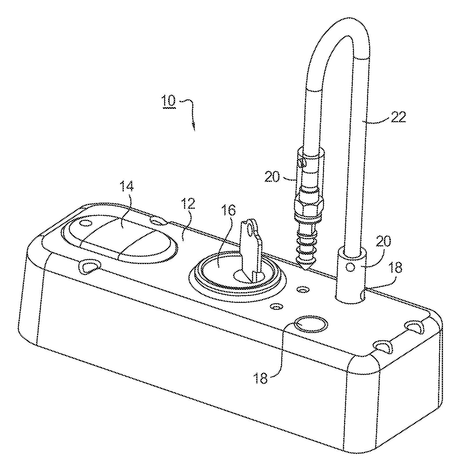
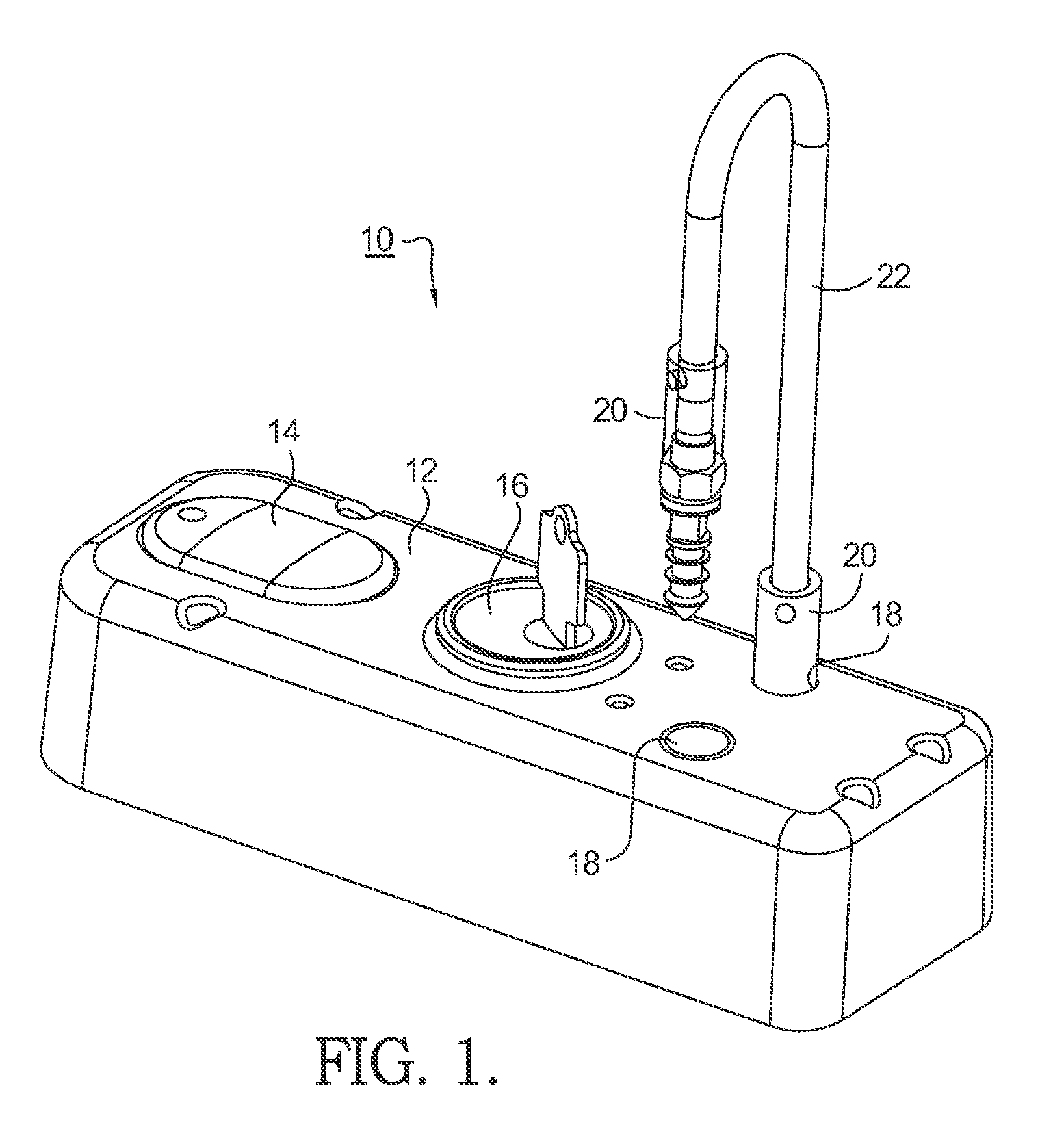
[0033]Referring to FIGS. 1 through 3 and FIG. 3A, a first embodiment 10 of an electronic cable lock system in accordance with the present invention comprises a housing cover 12 having a card / credential reader module 14, a barrel lock cylinder 16 for manual operation, and two openings 18 for receiving a cable plug assembly 20 attached to either end of a cable 22. Cable 22 may be comprised of several individual strands of wire wrapped tightly together such as shown in FIG. 3A and commonly referred to as aircraft cable. In one aspect of the invention, the cable itself may be configured as a conductor covered with a high strength stainless steel flexible casing.

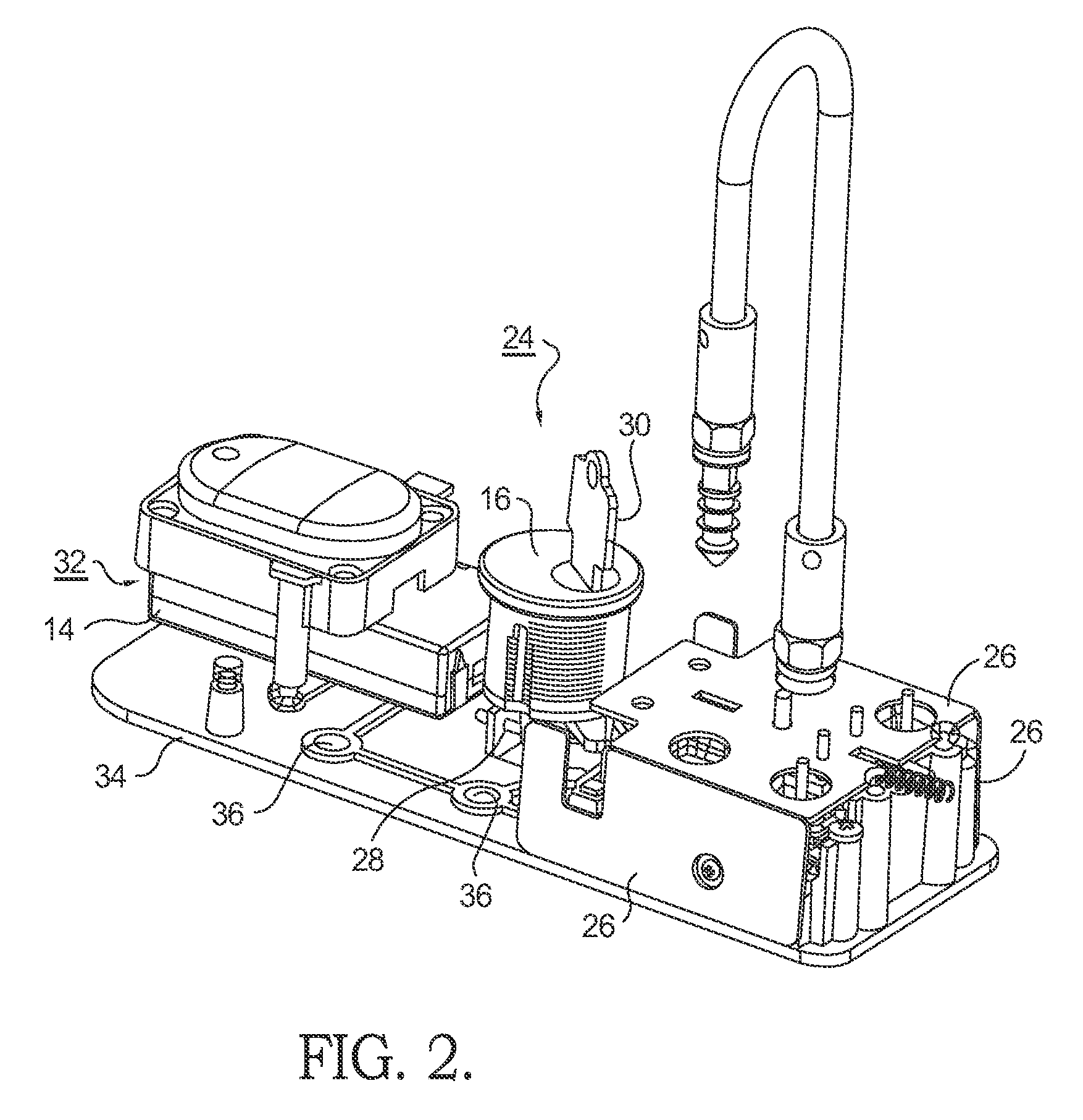
[0034]A partially exposed internal structure of the cable lock mechanism 24 shown in FIG. 2 includes three hardened sheet metal plates 26 to provide security against drilling. A micro-switch 28 or similar detector provides an indication whether a proper key 30 has been inserted into cylinder 16 and rotated. A microcontroller 32 i...


PUM

PropertyMeasurementUnit
electromechanicalaaaaaaaaaa
movementaaaaaaaaaa
non-conductiveaaaaaaaaaa

Abstract

An electromechanical cable lock system comprising an electromechanical locking mechanism including a cable having at least one plug end receivable in the locking mechanism and a plurality of slidable locking plates engageable with the plug in said locking mechanism. At least one of the locking plates is capable of movement in a first direction different from the movement of a second of said locking plates in a second direction. The locking plates are driven by a motor-driven cam mechanism. The system includes a card reader or other credential verifying device and an electronic controller for activating the locking mechanism, The system also includes a barrel lock for over-riding the electronic controller. A plurality of features can detect and alarm in the event of tampering or unauthorized entry.

Description

[0001]This application claims the benefit of U.S. Provisional Application No. 61 / 536,014, filed Sep. 18, 2011.TECHNICAL FIELD[0002]The present invention relates to lock systems employing a locking element including a flexible cable; more particularly, to an electromechanical lock system employing a cable; and most particularly, to such a system having a plurality of mode options for activating the locking mechanism and a plurality of different mechanisms for defeating attack.BACKGROUND OF THE INVENTION[0003]Locking systems employing a flexible cable are well known. In such a system, a tamper-resistant cable is threadable through an opening in the item(s) to be secured and may be lockably attached at both cable ends to prevent unwanted removal of the item from the cable and the premises. Some prior art cable lock systems are as simple as having loops formed on each end of the cable secured by a keyed padlock or a combination lock. Other cable lock systems may include a simple lock ca...

Claims


Application Information

Patent Timeline
Patent Type & Authority Patents(United States)
IPC IPC(8): E05B67/06B23P11/00E05B45/00E05B21/06E05B47/00E05B73/00E05B67/00G07C9/00E05B1/00E05B15/16E05B45/10E05B17/20E05B21/00
CPCE05B67/003B23P11/00E05B21/06E05B45/005E05B47/0012E05B73/0005G07C9/00944E05B1/00E05B15/1614E05B17/2084E05B21/00E05B45/10E05B47/00E05B2047/0086Y10T29/49833Y10T70/402
Inventor WHEELER, THOMAS J.WHIPPLE, BRIAN A.WEBB, MICHAEL A.PEABODY, JOSHUA T.PETERSEN, MATTHEW LYNNLEWIS, ROBERT WILLIAMCHOW, WILLIAM CHUNGSUMSULLIVAN, SCOTT PATRICK
Owner HANCHETT ENTRY SYST
Learn More