
System for characterizing manual welding operations

a technology for manual welding and operations, applied in auxillary welding devices, instruments, soldering apparatuses, etc., can solve the problem that the field lacks practical commercially available tools to track the performance of manual processes, and achieve the effect of improving the image signal-to-noise ratio

Active Publication Date: 2015-12-29
LINCOLN GLOBAL INC
View PDF472 Cites 51 Cited by
  • Summary
  • Abstract
  • Description
  • Claims
  • Application Information

AI Technical Summary

Benefits of technology

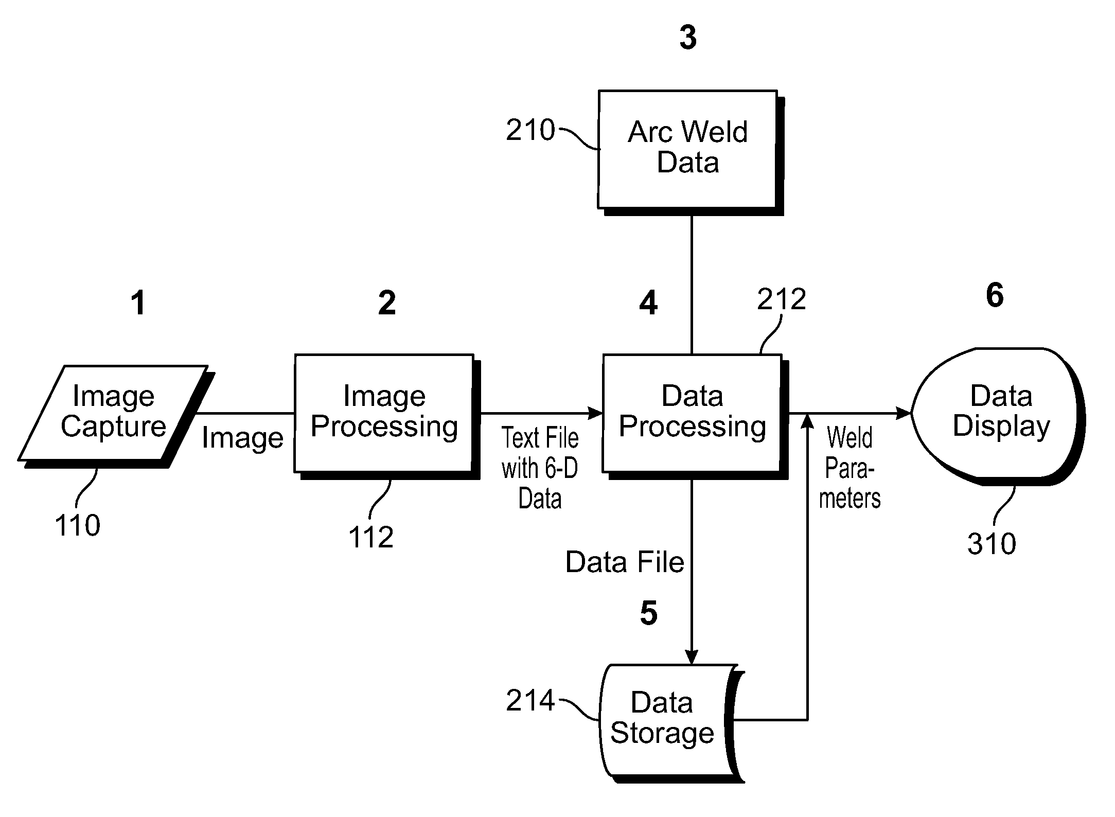
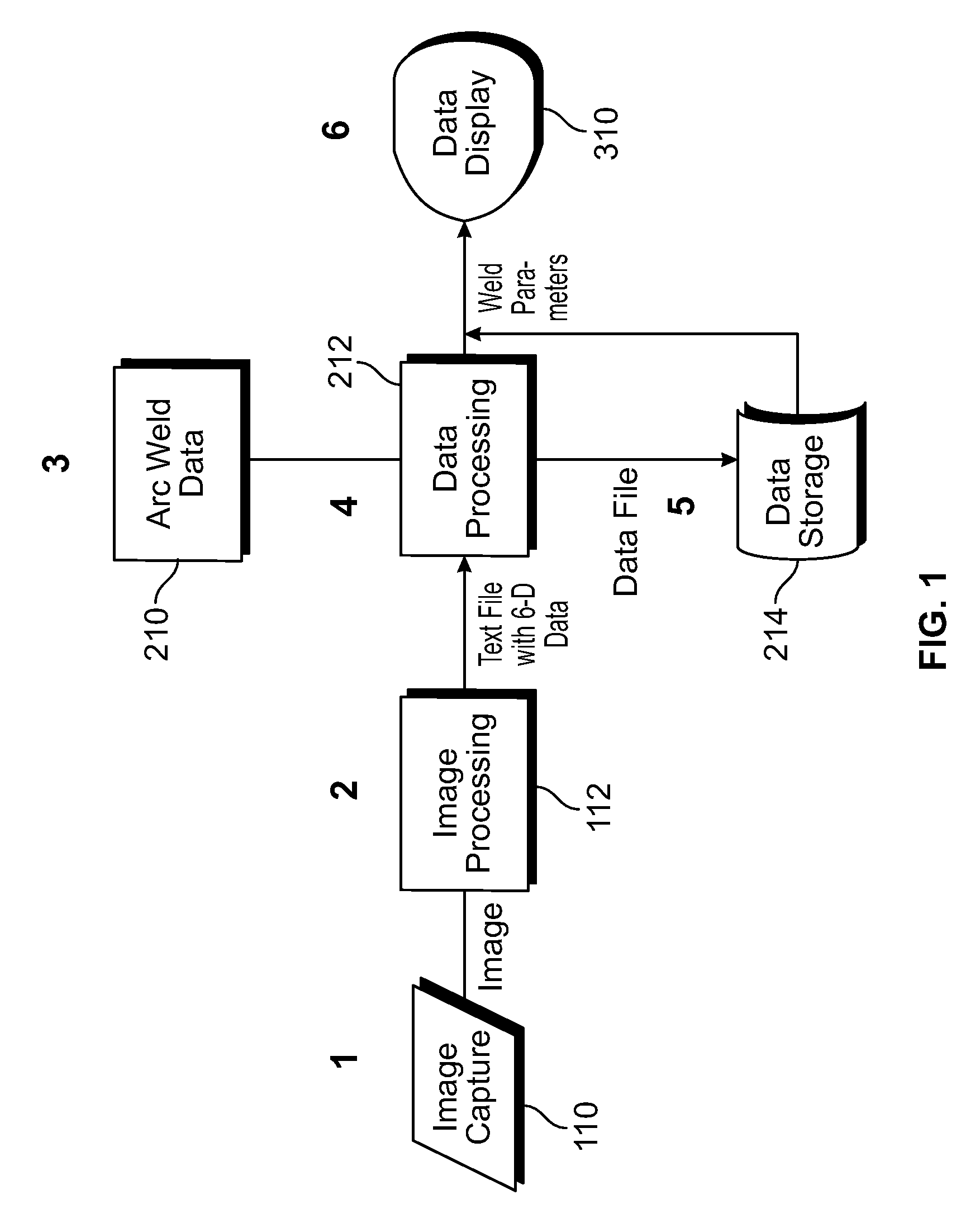
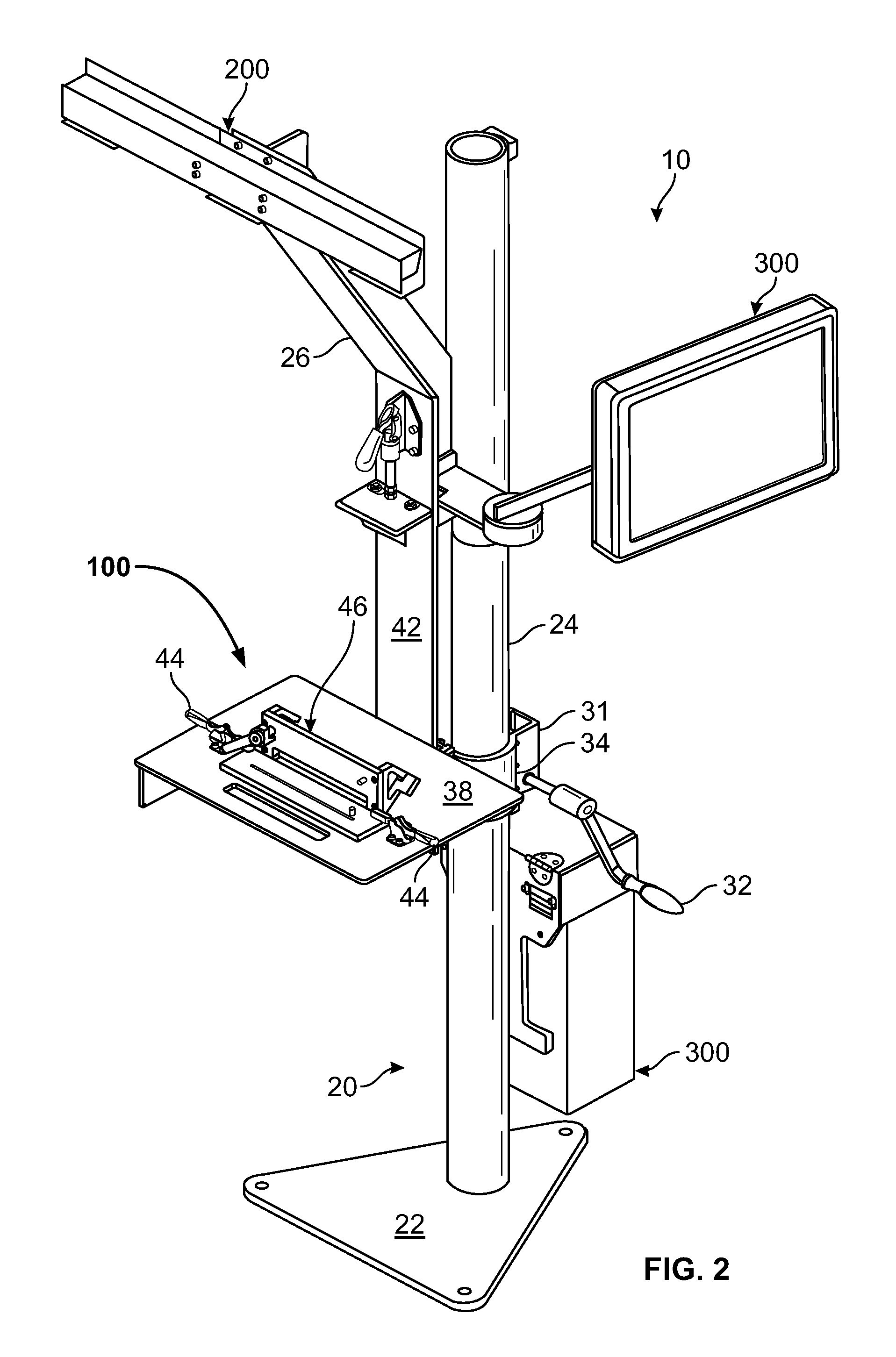
The present invention provides a system for characterizing manual and / or semiautomatic welding operations and exercises. The system includes a data generating component for generating data, a data capturing component for capturing the data, and a data processing component for analyzing the data. The data capturing component includes a fixture with pre-determined geometric characteristics, a workpiece containing at least one joint to be welded, and a calibration device with markers that define an operation path. The system also includes a welding tool with a target attached, which has a predetermined pattern of markers mounted thereon in a rigid body. The data processing component calculates the position and orientation of the operation path relative to the rigid body, the position of the tool point and tool vector relative to the rigid body, and the position of the tool point and tool vector relative to the operation path. This system helps improve the accuracy and efficiency of welding processes.

Problems solved by technology

To date, the majority of welding processes are performed manually, yet the field is lacking practical commercially available tools to track the performance of these manual processes.

Method used


Image

  • System for characterizing manual welding operations
  • System for characterizing manual welding operations
  • System for characterizing manual welding operations

Examples


Embodiment Construction

[0021]Exemplary embodiments of the present invention are now described with reference to the Figures. Reference numerals are used throughout the detailed description to refer to the various elements and structures. In other instances, well-known structures and devices are shown in block diagram form for purposes of simplifying the description. Although the following detailed description contains many specifics for the purposes of illustration, a person of ordinary skill in the art will appreciate that many variations and alterations to the following details are within the scope of the invention. Accordingly, the following embodiments of the invention are set forth without any loss of generality to, and without imposing limitations upon, the claimed invention.

[0022]The present invention relates to an advanced system for observing and characterizing manual welding exercises and operations. This system is particularly useful for welding instruction and welder training that provides an ...


PUM

PropertyMeasurementUnit
wavelengthsaaaaaaaaaa
velocityaaaaaaaaaa
accelerationaaaaaaaaaa

Abstract

A system for characterizing manual welding exercises and providing valuable training to welders that includes components for generating, capturing, and processing data. The data generating component further includes a fixture, workpiece, at least one calibration devices each having at least two point markers integral therewith, and a welding tool. The data capturing component further includes an imaging system for capturing images of the point markers and the data processing component is operative to receive information from the data capturing component and perform various position and orientation calculations.

Description

CROSS-REFERENCE TO RELATED APPLICATIONS[0001]This patent application is a continuation-in-part of U.S. patent application Ser. No. 12 / 499,687 filed on Jul. 8, 2009 and entitled “Method and System for Monitoring and Characterizing the Creation of a Manual Weld” and U.S. patent application Ser. No. 12 / 966,570 filed on Dec. 13, 2010 and entitled “Welding Training System”, the disclosures of which are hereby incorporated by reference herein in their entirety and made part of the present U.S. utility patent application for all purposes.BACKGROUND OF THE INVENTION[0002]The described invention relates in general to a system for characterizing manual welding operations, and more specifically to a system for providing useful information to a welding trainee by capturing, processing, and presenting in a viewable format, data generated by the welding trainee in manually executing an actual weld in real time.[0003]The manufacturing industry's desire for efficient and economical welder training ...

Claims


Application Information

Patent Timeline
Patent Type & Authority Patents(United States)
IPC IPC(8): G09B19/00B23K9/29B23K9/16B23K9/095B23K9/32G09B25/02G09B19/24B23K37/047B23K31/12B23K37/04
CPCB23K9/0956B23K9/16B23K9/291B23K9/32G09B25/02B23K37/04B23K37/047G09B19/24B23K31/125
Inventor CONRARDY, CHRISTOPHER C.BOULWARE, PAUL C.
Owner LINCOLN GLOBAL INC
Learn More