Numerical controller with workpiece setting error compensation unit for multi-axis machine tool

a multi-axis machine tool and compensation unit technology, applied in the direction of electric programme control, program control, instruments, etc., can solve the problems of inapplicability to numerical controllers, increased machining time and deformation of machined surfaces, and streaked machined surfaces, etc., to achieve correct and accurate machining, shorten the time without machining errors, and facilitate machining

Active Publication Date: 2015-12-29
FANUC LTD
View PDF17 Cites 3 Cited by
  • Summary
  • Abstract
  • Description
  • Claims
  • Application Information

AI Technical Summary

Benefits of technology

[0012]An object of the present invention is to provide a numerical controller for controlling a multi-axis machine tool having a mechanism for rotating a table or tool head using at least three linear axes and three rotating axes for machining the workpiece attached to the table, the numerical controller including a workpiece setting error compensation unit for compensating a setting error that arises when a workpiece is set. Furthermore, when a workpiece setting error is compensated in a multi-axis machine tool having at least three linear axes and three rotating axes, the numerical controller according to the present invention can avoid large motions that occur near singular points in five-axis machine tools. Consequently, the numerical controller enables machining with higher quality and accuracy in a shorter time.
[0020]According to the present invention, it is possible to provide a numerical controller that enables a multi-axis machine tool having at least three linear axes and three rotating axes to achieve correct and accurate machining as commanded even if a workpiece setting error arises when the workpiece is set.
[0021]Furthermore, according to the present invention, in a multi-axis machine tool having three rotating axes, it is possible to select an appropriate solution that does not cause large motions near singular points by making use of the redundancy of one rotating axis out of innumerable solutions to compensate a workpiece setting error that arises when the workpiece is set. Consequently, it is possible to provide a numerical controller that enables machining with higher quality and accuracy in a shorter time without machining error by preventing large motions of rotating axes near singular points.
[0022]In this way, according to the present invention, it is possible to provide a numerical controller for controlling a multi-axis machine tool having at least three linear axes and three rotating axes, the numerical controller including a workpiece setting error compensation unit for enabling machining without machining error by compensating a setting error that arises when a workpiece is set and by preventing large motions of rotating axes near singular points.

Problems solved by technology

This technique is, however, inapplicable to a numerical controller because this patent reference does not describe which solution should be selected out of a plurality of solutions for rotating axis positions.
Large motions of rotating axes near singular points would result in disadvantages such as an increased machining time and a degraded machined surface such as an uneven and / or streaked machined surface.
This technique, however, causes a machining error because of a changed tool path.
The conventional techniques relating to the above five-axis machine tools are, therefore, difficult to apply to a multi-axis machine tool having three rotating axes.
Furthermore, five-axis machine tools have problems including large motions of rotating axes near singular points and machining errors as described above.

Method used


Image

  • Numerical controller with workpiece setting error compensation unit for multi-axis machine tool
  • Numerical controller with workpiece setting error compensation unit for multi-axis machine tool
  • Numerical controller with workpiece setting error compensation unit for multi-axis machine tool

Examples


first embodiment

[0035]Referring now to FIG. 6, workpiece setting error compensation in a mixed type multi-axis machine tool having one rotating axis for rotating the table and two rotating axes for rotating the head will be described.

[0036]This multi-axis machine tool is configured with, in addition to three linear axes X, Y, and Z, a B axis rotating around the Y axis and an A axis rotating around the X axis for rotating a tool head 21 and a C axis rotating around the Z axis for rotating a rotary table 22. In FIG. 6, reference numeral 23 denotes a tool.

[0037]The actual workpiece position is deviated from the reference workpiece position due to inclination of the table or the workpiece that is deviated when the workpiece is set. The amounts of deviation are measured in advance and set, with respect to the workpiece setting coordinate system, as translational error amounts (δx, δy, δz) along the X, Y, and Z axes, a rotational error amount (α) around the X axis, a rotational error amount (β) around th...

second embodiment

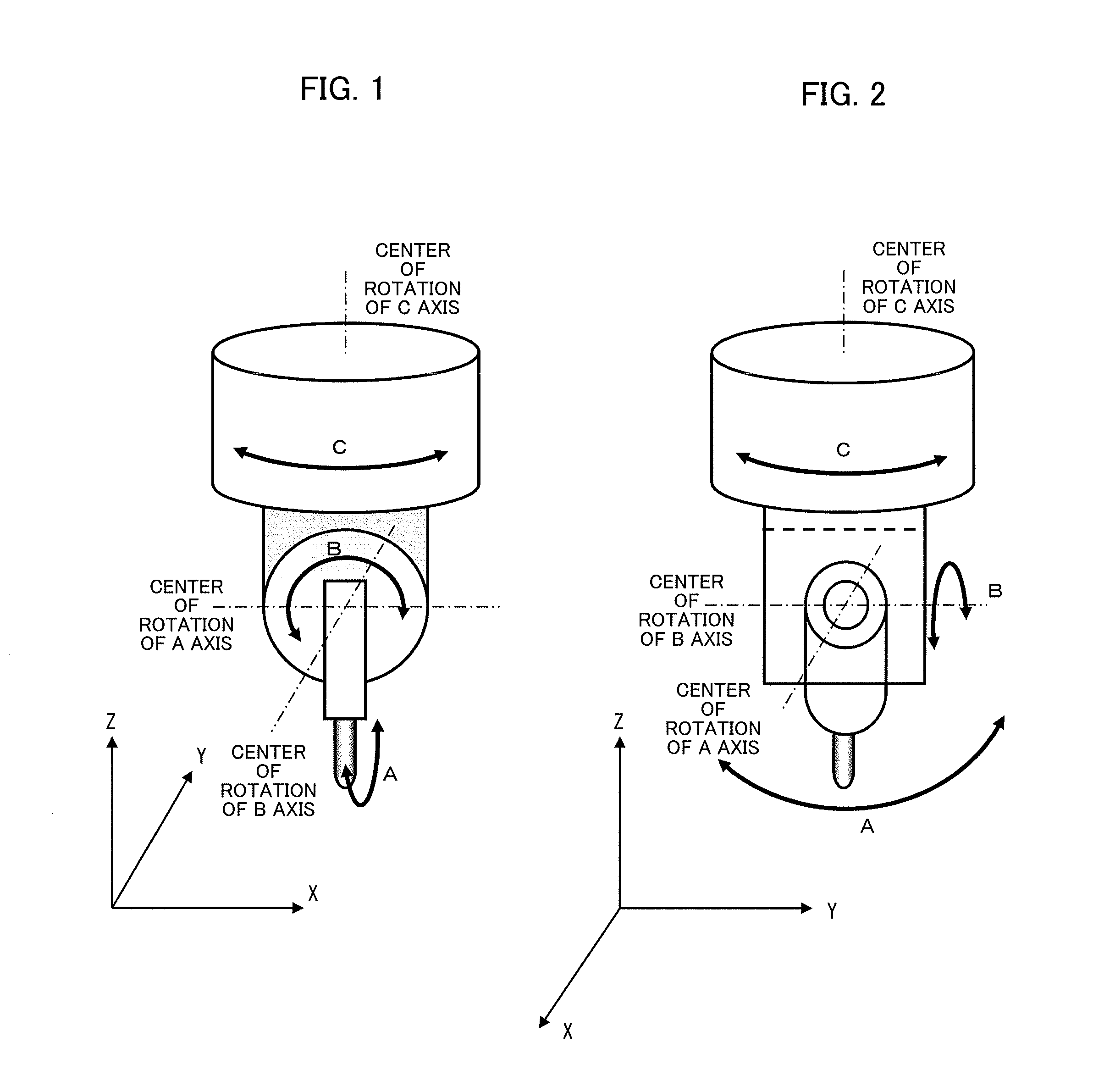
[0075]Described below is workpiece setting error compensation in a tool head rotation type multi-axis machine tool having three rotating axes for rotating the tool head (see FIGS. 1 and 2).

[0076]Since the rotating axes are arranged in the order of A, B, and C axes from the tool to the workpiece, equation (14) below is used instead of equation (1) above (furthermore, instead of equation (5) above). In addition, since there is no table rotating axis, equation (15) below is used instead of equation (2) above, and equation (16) below is used instead of equation (13) above.

[0077][iwjwkw]=[cos⁢⁢Cc-sin⁢⁢Cc0sin⁢⁢Cccos⁢⁢Cc0001]⁡[cos⁢⁢Bc0sin⁢⁢Bc010-sin⁢⁢Bc0cos⁢⁢Bc]⁢ [1000cos⁢⁢Ac-sin⁢⁢Ac0sin⁢⁢Accos⁢⁢Ac]⁡[001](14)[xwywzw]=[XcYcZc]-[x⁢⁢0y⁢⁢0z⁢⁢0](15)[xyz]=[xayaza]+[x⁢⁢0y⁢⁢0z⁢⁢0](16)

[0078]The subsequent calculations are the same as in the above first embodiment and therefore description thereof will be omitted.

third embodiment

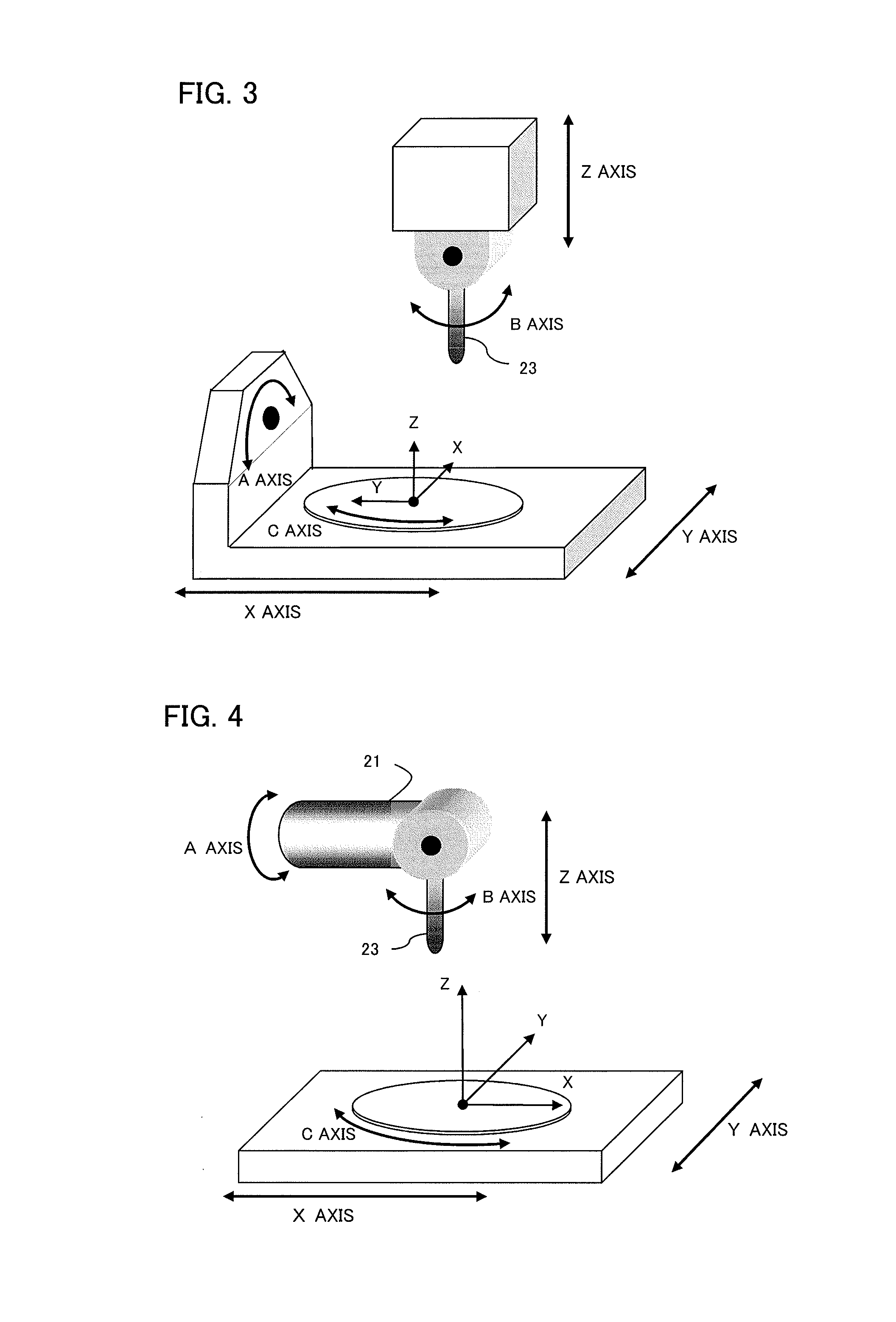
[0079]Described below is workpiece setting error compensation in a mixed type multi-axis machine tool having two rotating axes for rotating the table and one rotating axis for rotating the head (see FIG. 3).

[0080]Since the rotating axes are arranged in the order of B, A, and C axes from the tool to the workpiece, equation (1) above is the same as in the first embodiment (equation (5) is also the same). In addition, since the two rotating axes for rotating the table are A and C axes, equation (17) below is used instead of equation (2) above and equation (18) below is used instead of equation (13) above.

[0081][xwywzw]=[cos⁢⁢Cc-sin⁢⁢Cc0sin⁢⁢Cccos⁢⁢Cc0001]⁡[1000cos⁢⁢Ac-sin⁢⁢Ac0sin⁢⁢Accos⁢⁢Ac]⁡[Xc-x⁢⁢0Yc-y⁢⁢0Zc-z⁢⁢0](17)[xyz]=[1000cos⁢⁢asin⁢⁢a0-sin⁢⁢acos⁢⁢a]⁡[cos⁢⁢csin⁢⁢c0-sin⁢⁢ccos⁢⁢c0001]⁡[xayaza]+[x⁢⁢0y⁢⁢0z⁢⁢0](18)

[0082]The subsequent calculations are the same as in the first embodiment described above and therefore description thereof will be omitted.


PUM


Abstract

A numerical controller for controlling a multi-axis machine tool for machining with three linear axes and three rotating axes has a function for compensating a setting error that arises when a workpiece is set. This numerical controller determines compensated linear axis positions of the three linear axes and compensated rotating axis positions of the three rotating axes by calculating compensated tool position and direction depending on the setting error such that the tool position and direction on the workpiece setting coordinate system are maintained on the workpiece having such a setting error, and drives and controls the axes according to the compensated linear axis positions and compensated rotating axis positions.

Description

RELATED APPLICATION DATA[0001]This application claims priority under 35 U.S.C. §119 and / or §365 to Japanese Application No. 2011-195234 filed Sep. 7, 2011, the entire contents of which are incorporated herein by reference.BACKGROUND OF THE INVENTION[0002]1. Field of the Invention[0003]The present invention relates to a numerical controller for controlling a multi-axis machine tool (multi-axis processing machine) for machining a workpiece (item to be machined) attached to a table using a mechanism for rotating a table or tool head using at least three linear axes and three rotating axes, and in particular to a numerical controller including a workpiece setting error compensation unit for compensating a setting error that arises when a workpiece is set.[0004]2. Description of the Related Art[0005]Five-axis machine tools having two rotating axes in addition to three linear axes (X, Y, and Z axes) are coming into widespread use. Numerical controllers including a workpiece setting error ...

Claims


Application Information

Patent Timeline
Patent Type & Authority Patents(United States)
IPC IPC(8): G05B19/18G05B19/404
CPCG05B19/404
Inventor OTSUKI, TOSHIAKI
Owner FANUC LTD
Why Eureka
Try Eureka