Magnetic confinement for microbeam radiation damage area

a radiation damage area and magnetic confinement technology, applied in radiation therapy, x-ray/gamma-ray/particle irradiation therapy, therapy, etc., can solve the problems of not providing a radiation therapy method, patients often take many days and weeks to complete the treatment, and cannot be completely satisfactory and effective in all instances. , to achieve the effect of quick yet safe treatment of patients

Active Publication Date: 2016-01-12
COPERNICUS DYNAMICS GRP LP
View PDF7 Cites 15 Cited by
  • Summary
  • Abstract
  • Description
  • Claims
  • Application Information

AI Technical Summary

Benefits of technology

[0013]Accordingly, there is a need for improved radiation therapies that can quickly yet safely treat patients. Further there is a need to confine radiation doses in desired peak dosage areas will minimizing radiation doses in desired valley dosage areas.

Problems solved by technology

Radiation therapy has also exhibited favorable results in many cases, while failing to be completely satisfactory and effective in all instances.
Although other methods and processes are known for radiation therapy, none provides a method for performing radiation therapy while avoiding significant radiation-induced damage to tissues proximal to, distal to, and interspersed with the targeted lesion.
Present radiation therapies often take many days and weeks of treatment to provide enough radiation to a target tumor.
Some of these electrons will stay within the boundaries of the width of the irradiated area, which corresponds to a desired treatment area, while others will exit this area, and hence potentially damage untreated tissue.
Widening of the penumbra (blurring at the edge between the peak and valley regions) is detrimental to the desired dose delivery and can: harm the adjacent healthy tissues; limit useful microbeam treatment depth; limit depths of tumors below the skin; limit the types of tumor / lesions / conditions treated; and limit the usefulness of MBRS in general.
In some cases the spread of the radiation dose and / or damage region outside of the intended peak area would limit or prevent the usefulness of Microbeam treatment because of the detrimental effect of the radiation dose and / or damage in the unplanned valley regions.

Method used


Image

  • Magnetic confinement for microbeam radiation damage area
  • Magnetic confinement for microbeam radiation damage area
  • Magnetic confinement for microbeam radiation damage area

Examples


Embodiment Construction

[0022]Referring now to the drawings, in which like numerals refer to like components or steps, there are disclosed broad aspects of various exemplary embodiments.

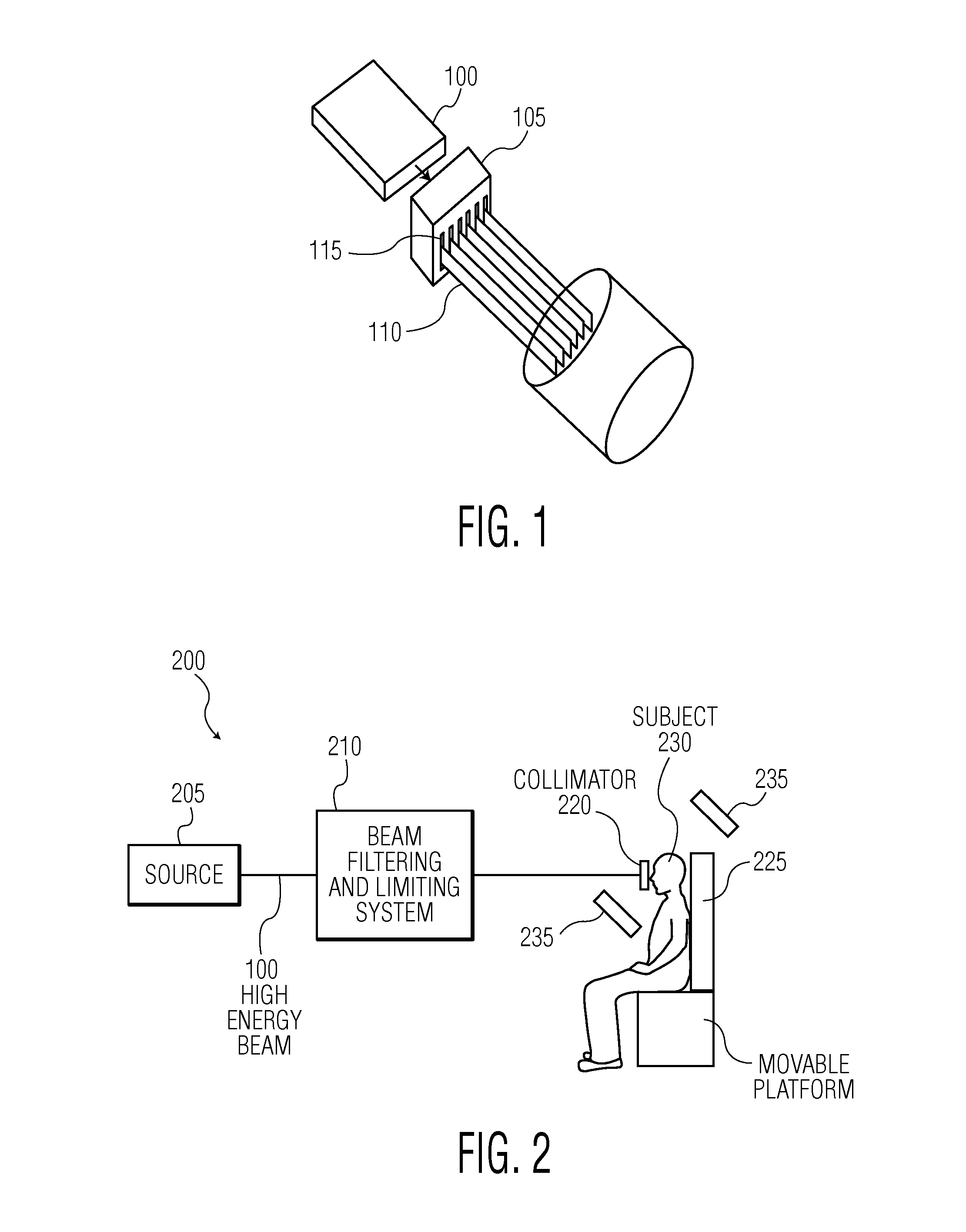
[0023]FIG. 1 illustrates a method for producing microbeams using a collimator. The collimator 105 may include a plurality of parallel slits 115 in a vertical direction. A high-energy radiation fan beam 100 that may be narrow in the vertical direction and wide in the horizontal direction may pass through the collimator 105. Because the collimator 105 is made of a high-Z material, it blocks portions of the incident x-ray radiation of the high-energy radiation fan beam 100. The portion of the high-energy radiation fan beam 100 that passes through the slits 115 of the collimator 105 forms the microbeams 110. The microbeams 110 may be used to treat a subject. Depending upon the vertical height of the fan beam 100 relative to the size of the treatment area, the subject may have to be moved relative to the microbeams 110 in order ...


PUM


Abstract

Various embodiments relate to a method of performing microbeam radiation therapy on a subject, including: producing a high-energy radiation beam in a first direction; producing planar microbeams using the high-energy radiation beam in the first direction, wherein the microbeams have a width, wherein the planar microbeams produce scattered electrons; and applying a magnetic field in a direction lying in a plane substantially parallel to the planar microbeams, wherein the strength of the magnetic field corresponds to the width of the microbeam.

Description

TECHNICAL FIELD[0001]Various exemplary embodiments disclosed herein relate generally to magnetic confinement for microbeam radiation damage area. Such application is especially useful in treating various cancers and other tumors and by concentration of the radiation to the selected area to be irradiated, and thus, reducing the radiation to areas not desired to be radiated.BACKGROUND[0002]Cancer continues to be one of the foremost health problems. Conventional treatments such as surgery and chemotherapy have been extremely successful in certain cases; in other instances, much less so. Radiation therapy has also exhibited favorable results in many cases, while failing to be completely satisfactory and effective in all instances. An alternative form of radiation therapy, known as microbeam radiation therapy (MBRS) or microbeam radiosurgery (MBRS) may be used to treat certain tumors for which the conventional methods have been ineffective.[0003]MBRS differs from conventional radiation t...

Claims


Application Information

Patent Timeline
Patent Type & Authority Patents(United States)
IPC IPC(8): A61N5/10
CPCA61N5/1042A61N2005/1095
Inventor SLATKIN, DANIEL N.GEISLER, FRED HARDEN
Owner COPERNICUS DYNAMICS GRP LP
Why Eureka
Try Eureka