Automated re-focusing of interferometric reference mirror

Active Publication Date: 2016-01-12
BRUKER NANO INC
View PDF2 Cites 2 Cited by
  • Summary
  • Abstract
  • Description
  • Claims
  • Application Information

AI Technical Summary

Benefits of technology

[0009]Those skilled in the art will readily appreciate that the plot of parameter-of-interest versus reference-mirror-position for the reference surface can be carried out automatically by programming the same processor used to carry out VSI or PSI measurements. Therefore, the development of such an empirical relationship between the values of the measured parameter and mirror position enables the automated recalibration of the system to re-focus the mirror in automated fashion to correct drifts caused by environmental factors. Appropriate hardware may be added to conventional systems to monitor the occurrence of the quality-control event, to translate the reference mirror for calibration measurements and in-focus positioning, and to control the various process steps according to the invention.
[0010]It is also understood that variations of the process steps may be required to carry out the invention depending on the exact interferometric method used to measure parts.

Problems solved by technology

Thus, the process of recalibration of an interferometric instrument is slow and unsuited for online testing of parts for quality-control purposes, where the measured parameters are expected to be essentially the same during repeated measurements.
Therefore, when environmental factors affect the initial calibration of the interferometer that ensures this OPD/focus condition, the quality of the measurements deteriorates

Method used


Image

  • Automated re-focusing of interferometric reference mirror
  • Automated re-focusing of interferometric reference mirror
  • Automated re-focusing of interferometric reference mirror

Examples


Embodiment Construction

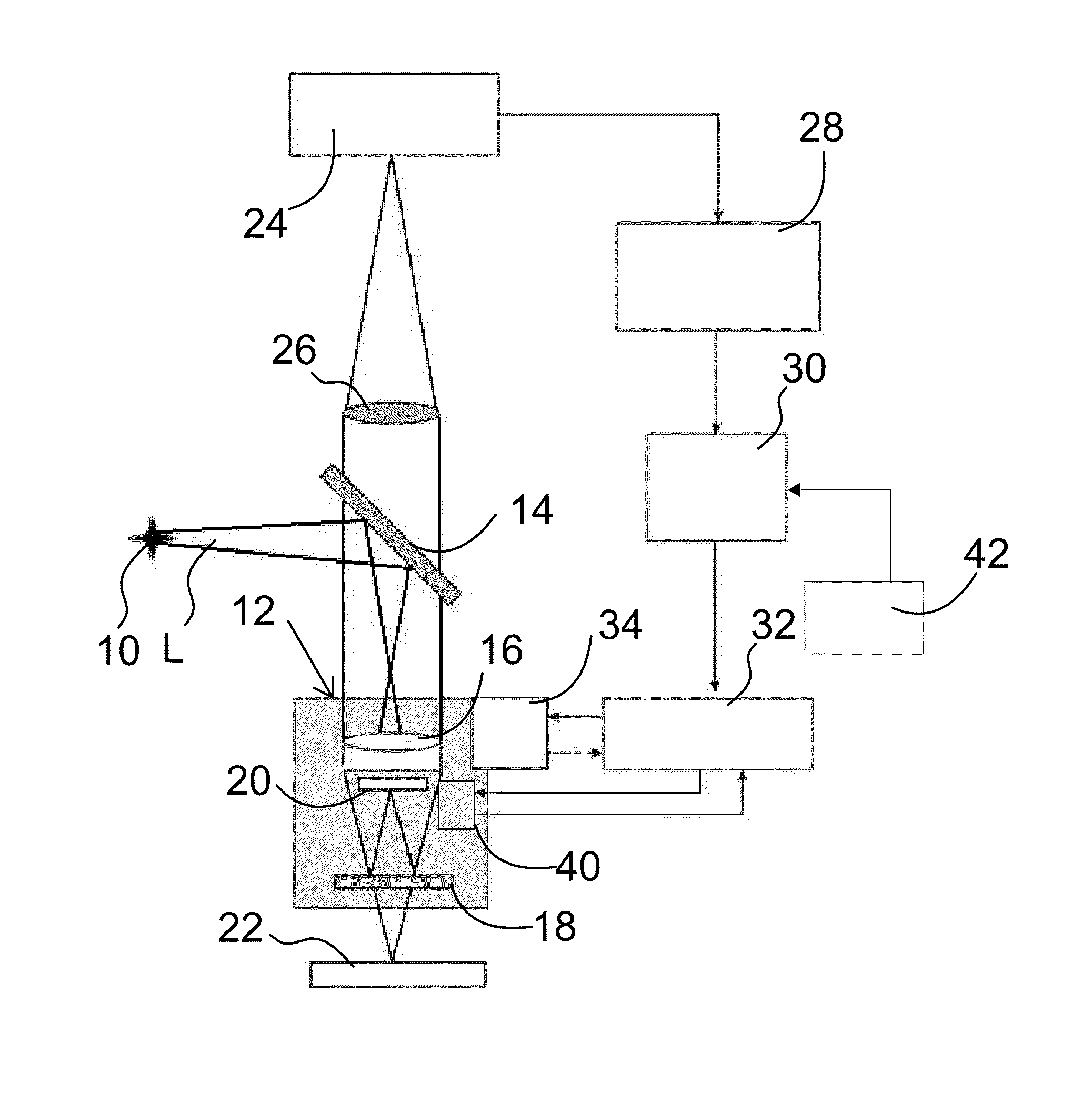
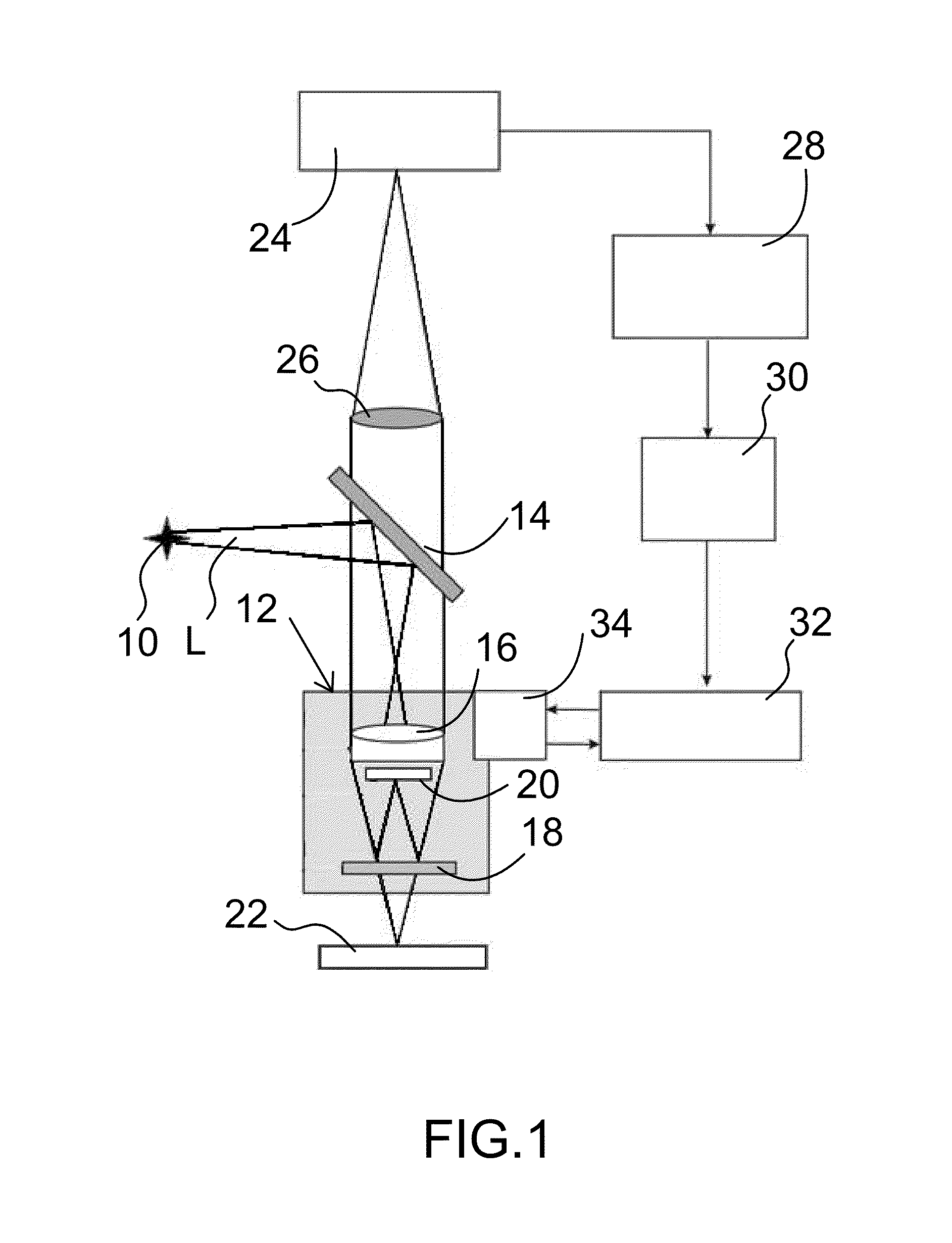
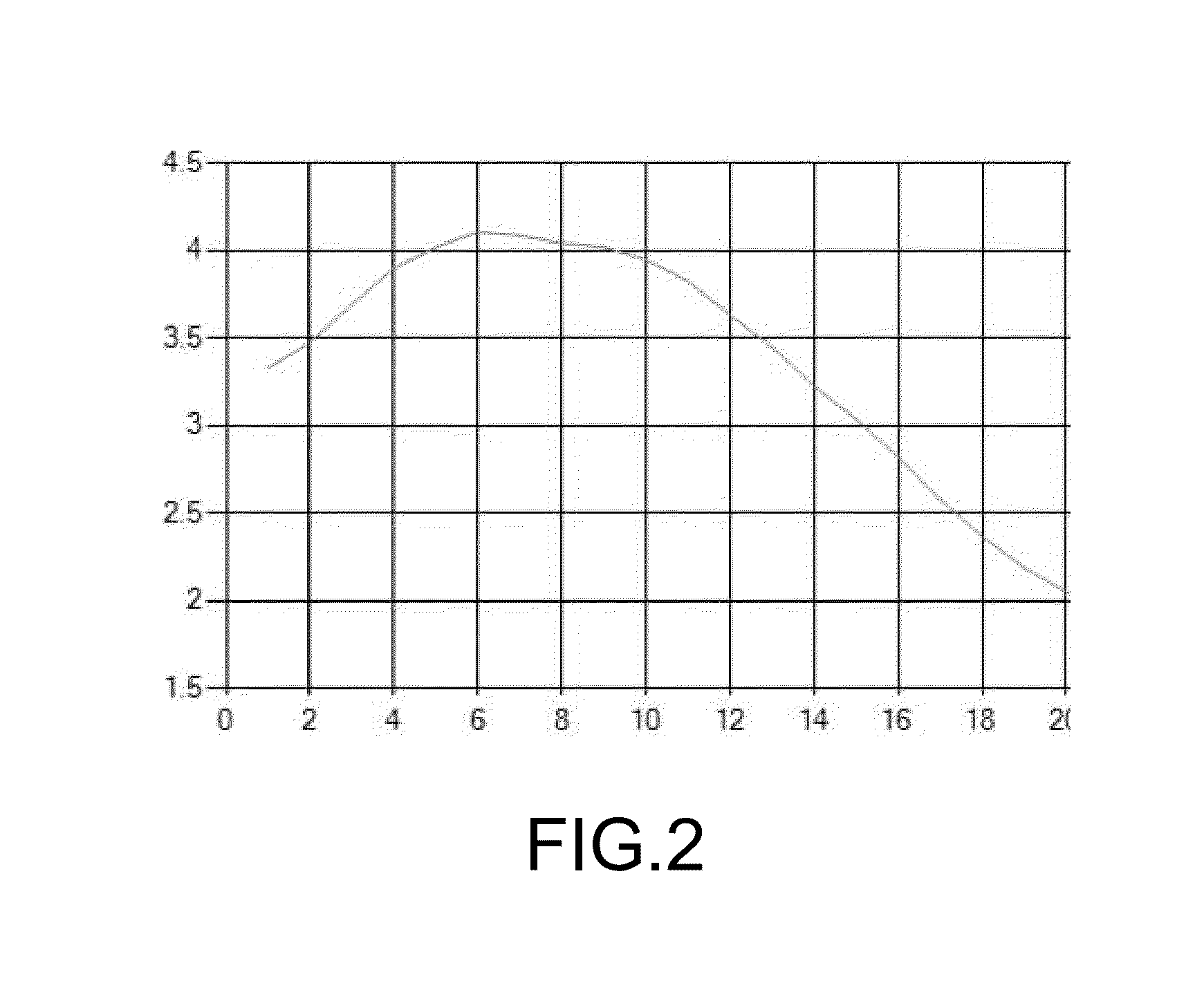
[0020]The invention is a procedure for adjusting the position of the reference mirror of an interferometric objective relative to the objective lens in order to re-focus the mirror when necessary as a result of drifts caused by environmental effects. The procedure is based on the development of an empirical relationship between mirror position and the values of a measured parameter, such as roughness or modulation, wherein the relationship is used as an indicator of best focus. A plot reflecting such relationship is used periodically or at predetermined quality-control events, if necessary, to re-focus automatically the reference mirror during periods of repeated measurements preferably of the same type of part, such as the air-bearing surface (ABS) of a magnetic head or a light-emitting-diode (LED) component.

[0021]The invention is applicable to any configuration of interferometric apparatus that includes a beam splitter propagating light toward a reference arm and a test arm. A Mir...


PUM


Abstract

A reference surface is used to develop an empirical plot between a parameter of interest, such as roughness or modulation, and the position of the reference mirror in an interferometer by repeating measurements of the reference surface at different positions of the reference mirror so as to identify the in-focus position of the reference mirror. Serial quality-control measurements of samples of interest are carried out with the reference mirror in such in-focus position until a predetermined quality-control event triggers an automated system re-calibration by re-measuring the reference surface and, if the result does not correspond to the in-focus position of the reference mirror according to the plot, by finding a new in-focus position for the reference mirror using the same plot or, alternatively, a new similarly produced plot. Sample measurements are then resumed with the mirror placed at that new position.

Description

BACKGROUND OF THE INVENTION[0001]1. Field of the Invention[0002]This invention pertains to the general field of interferometric metrology. In particular, it pertains to an automated method for periodically re-focusing the reference mirror of the interferometer to account for environmental changes during repeated interferometric measurements.[0003]2. Description of the Prior Art[0004]The interferometric objectives used in the art are usually off-the shelf components (such as produced by Nikon and Olympus) that allow manual adjustments to refocus the objective's reference mirror as needed to account for drift caused by environmental factors, such as temperature, humidity and vibrations. Thus, the process of recalibration of an interferometric instrument is slow and unsuited for online testing of parts for quality-control purposes, where the measured parameters are expected to be essentially the same during repeated measurements.[0005]As is well understood in the art, an interferometri...

Claims


Application Information

Patent Timeline
IPC IPC(8): G01B9/02G01M11/02
CPCG01M11/02G01B9/02063G01B9/02067G01B9/02072
Inventor NOVAK, ERIKFARRELL, COLINGUENTHER, BRYAN
Owner BRUKER NANO INC
Why Eureka
Try Eureka