Flow rate measuring apparatus

a flow rate and measuring device technology, applied in the direction of engine testing, structural/machine measurement, instruments, etc., can solve the problems of large dust with a particle diameter of 100 to 200 m, inability to remove 100 m or less of particles by purifying filters, and relatively small dust, etc., to achieve good balance between dust tolerance and flow rate detection accuracy, reduce collision energy, and high reliability

Active Publication Date: 2016-01-12
MITSUBISHI ELECTRIC CORP
View PDF24 Cites 8 Cited by
  • Summary
  • Abstract
  • Description
  • Claims
  • Application Information

AI Technical Summary

Benefits of technology

[0027]In order to solve the above problems, it is an object of the present invention to provide a highly reliable flow rate measuring apparatus that achieves a good balance between dust tolerance and flow rate detection accuracy by sufficiently decreasing collision energy of relatively large dust with a particle diameter of 100 to 200 μm or so among other dust contained in fluid to be measured to prevent a flow rate detecting device from being damaged by high speed collision of the dust with the flow rate detecting device.
[0029]According to the flow rate measuring apparatus in accordance with the invention, dust with various particle diameters entering the bypass passage, particularly, relatively large dust with a particle diameter of 100 to 200 μm or so, is reliably caused to collide with the first step-shaped part, the second step-shaped part and the plate-like member to be sufficiently decelerated and reach the flow rate detecting device with low collision energy, which can prevent the flow rate detecting device from being damaged by collision of dust at high speed. Furthermore, the placement position of the plate-like member is optimized to suppress turbulence of air moving toward the flow rate detecting device, which can provide a reliable flow rate measuring apparatus that achieves a good balance between flow rate detection accuracy and dust tolerance.

Problems solved by technology

However, relatively small dust, for example, with a particle diameter of 100 μm or less cannot be removed by a purifying filter in the air cleaner and gets mixed into intake air.
Furthermore, deterioration of the purifying filter, use of the purifying filter in a region with a severe usage condition, use of a substandard filter other than a proper product, or the like may cause relatively large dust with a particle diameter of 100 to 200 μm or so to get mixed into intake air.
When such dust is accelerated by intake air and collides with the flow rate detecting device at high speed, the flow rate detecting part may be damaged depending on the particle diameter or speed of the dust.
However, in the flow rate measuring apparatus of the Patent Documents 1 and 2, increasing the number of bends in the bypass passage increases pressure loss occurring in the bypass passage, thereby causing drift.
This causes turbulence in air moving toward the flow rate detecting device, thereby decreasing the flow rate detection accuracy.
Thus, only bending the bypass passage has difficulty in sufficiently reducing collision energy of dust while maintaining the flow rate detection accuracy.
Furthermore, the flow rate measuring apparatus of the Patent Document 3 has a problem that collision energy of relatively large dust with a particle diameter of 100 to 200 μm or so cannot be sufficiently reduced.
Also, providing fine bumps and dips on the wall surface of the bypass passage makes it easier for dust of several micrometers to adhere to the wall surface, which causes a problem of increase in characteristic variation due to contamination and a problem of not obtaining an intended effect due to bumps and dips covered with contaminant.
Furthermore, the flow rate measuring apparatus of the Patent Document 4 also has a problem that collision energy of dust with a particle diameter of 100 to 200 μm or so cannot be sufficiently reduced, similarly to that of the Patent Document 3.
Also, the sawtooth bumps and dips having an angle less than 90 degrees are likely to cause stagnation of air, which causes a problem of increase in pressure loss and a problem of decrease in the flow rate detection accuracy due to air turbulence.
Another problem is that small dust is likely to be deposited on the bumps and dips, and, when the bumps and dips are covered with the dust, an intended effect cannot be obtained.
Furthermore, the flow rate measuring apparatus of the Patent Document 5 includes the flow rate detecting device placed in the deepest part of the U-shaped sub-bypass passage, which has a problem that, when air containing dust is introduced into the sub-bypass passage, the airborne dust flies along the sub-bypass passage and generally perpendicularly collides with the flow rate detecting device.
Furthermore, in the flow rate measuring apparatus of the Patent Document 6, dust entering inside of the guide louver collides with the guide louver and then moves toward the flow rate detecting device, so collision with the flow rate detecting device cannot be avoided.
Another problem is that the guide louver mounted near the flow rate detecting device causes air turbulence, thereby significantly reducing the flow rate detection accuracy.
Furthermore, in the flow rate measuring apparatus of the Patent Document 7, the plate-like member is provided directly upstream of the flow rate detecting device, which provides an effect of smoothing the flow velocity vector against drift, but has a problem of increase in pressure loss and significant decrease in the speed of air flow in the bypass passage and a problem of large air turbulence directly downstream of the plate-like member causing decrease in the flow rate detection accuracy.

Method used


Image

  • Flow rate measuring apparatus
  • Flow rate measuring apparatus
  • Flow rate measuring apparatus

Examples


first embodiment

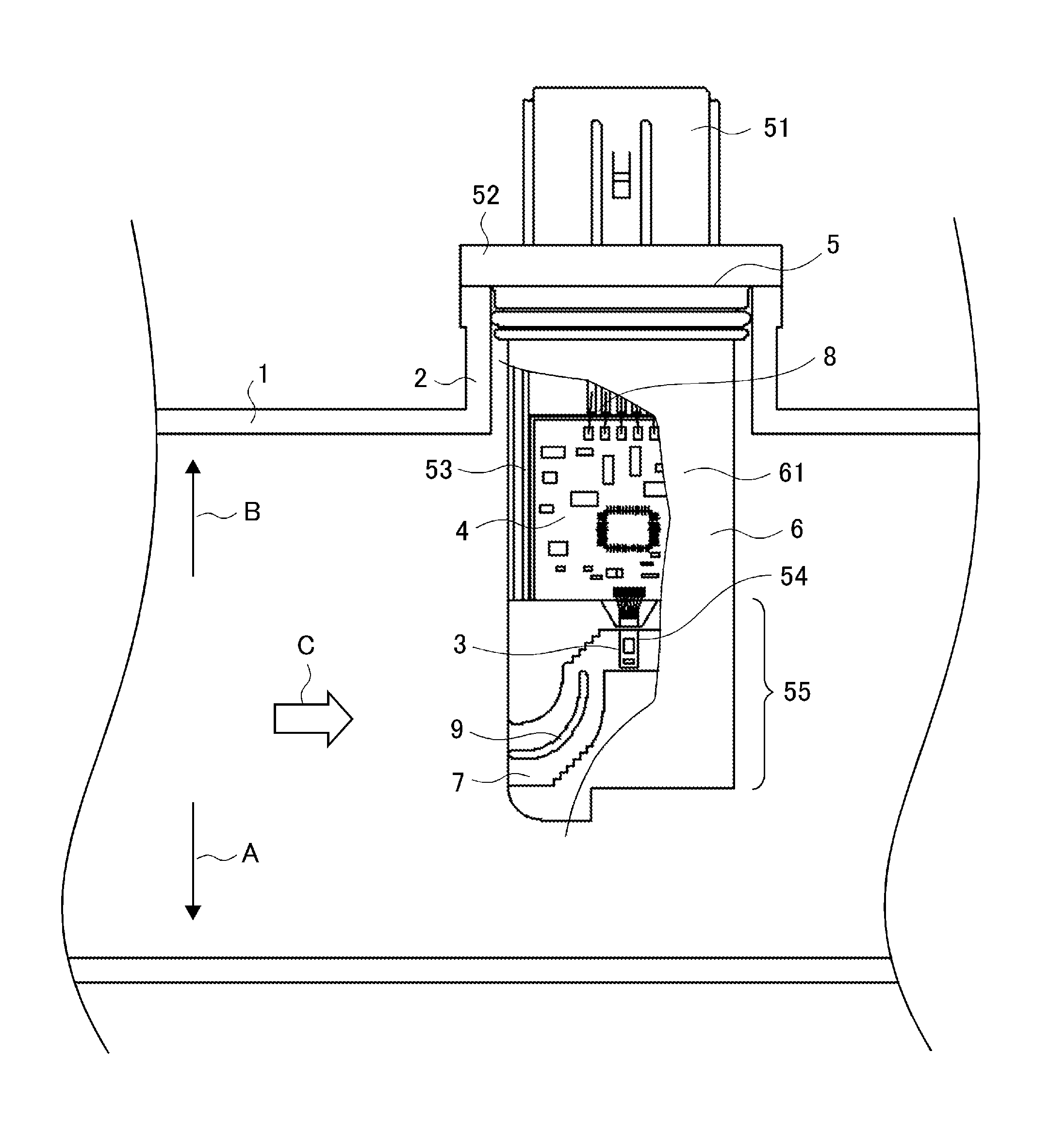
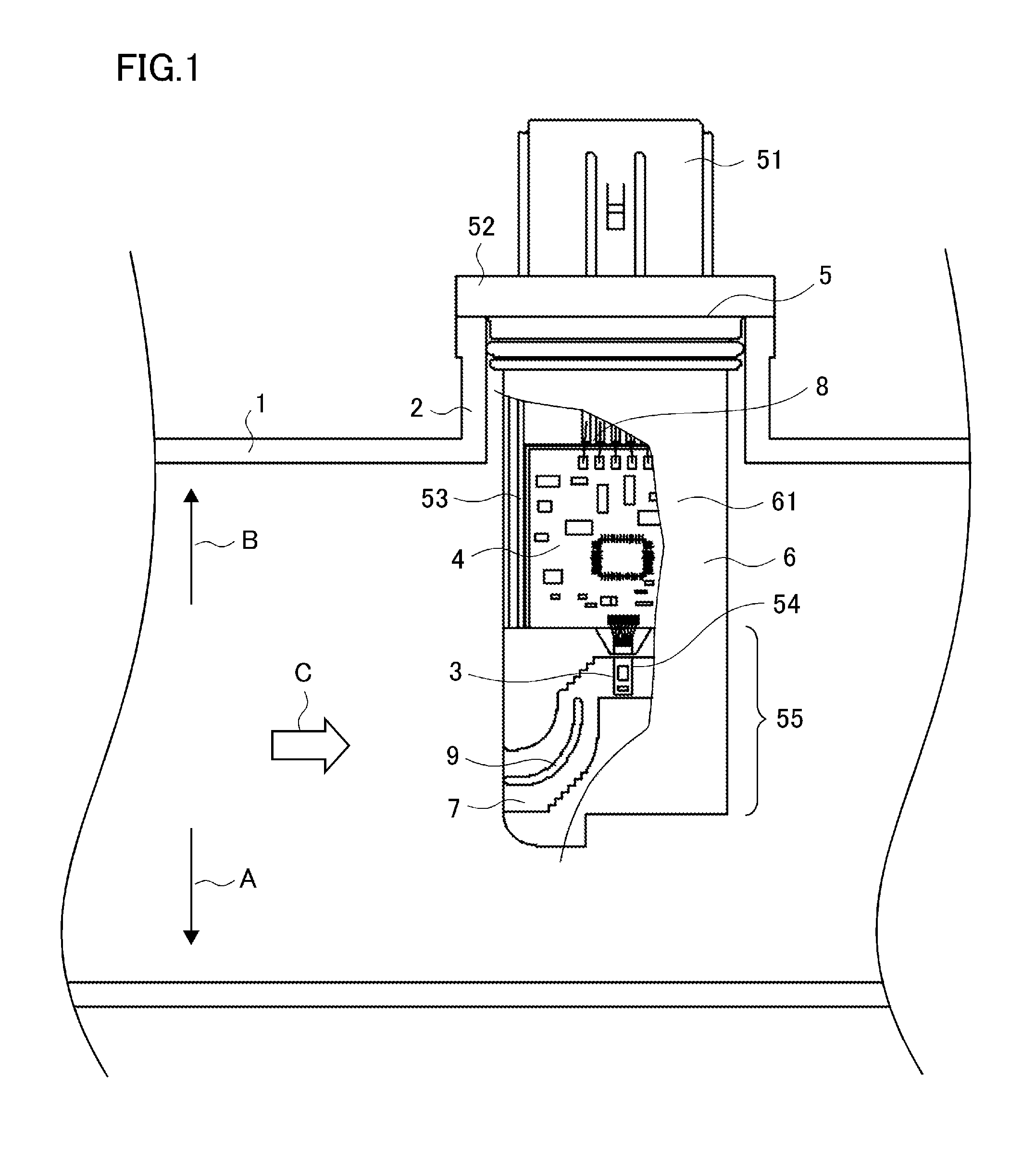
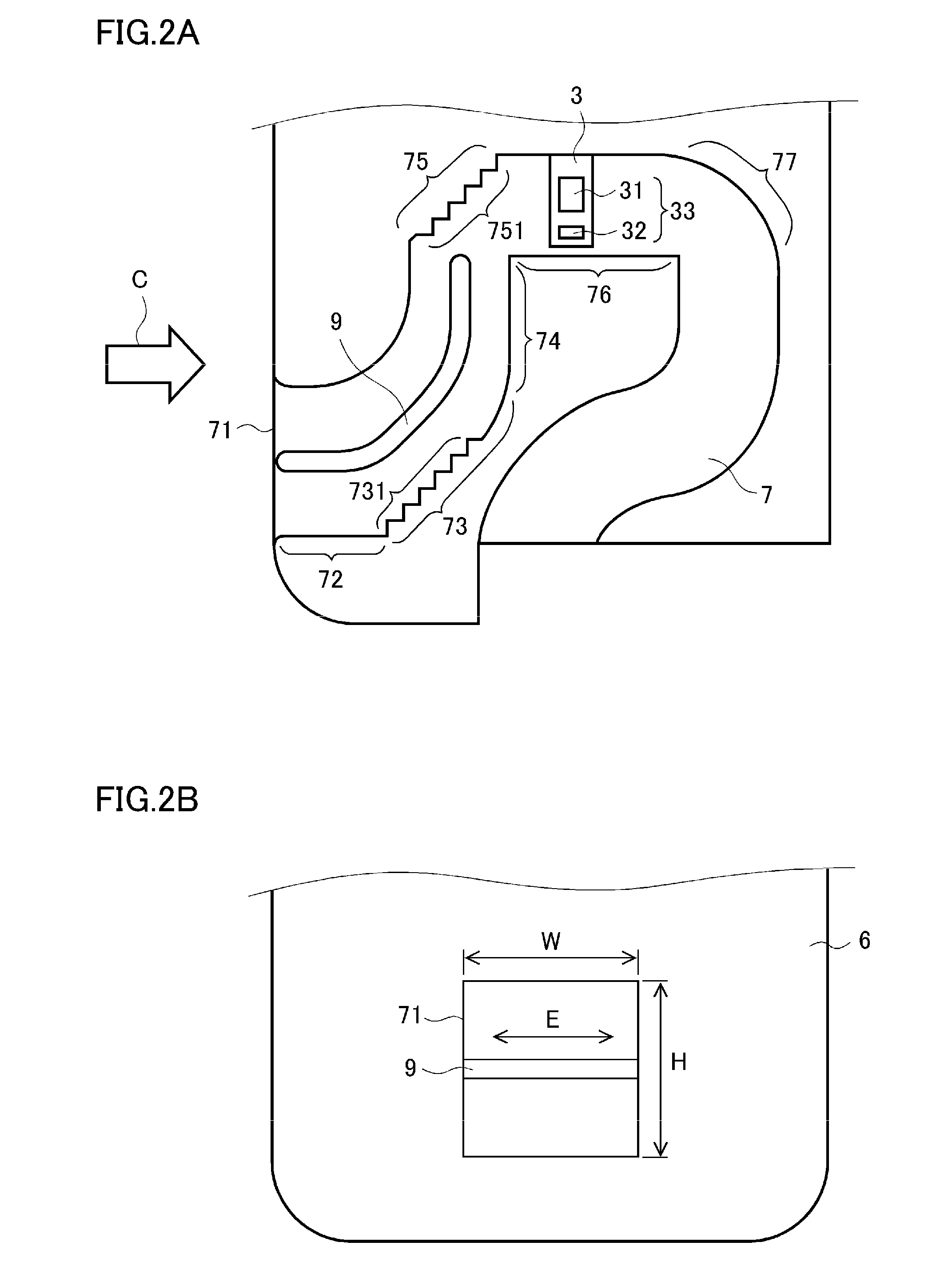
[0053]A flow rate measuring apparatus in accordance with a first embodiment of the invention is described below with reference to the drawings. FIG. 1 is a partially cutaway front view of the flow rate measuring apparatus in accordance with the first embodiment. FIG. 2A is a front view and FIG. 2B is a side view of the flow rate measuring apparatus in accordance with the first embodiment in which a bypass passage and its surroundings are enlarged. Note that, through all the drawings referred to in the following description, the same or corresponding components are denoted by the same reference numerals.

[0054]The flow rate measuring apparatus in accordance with the first embodiment measures flow rate of fluid to be measured passing through a pipe. For example, as shown in FIG. 1, when intake air passing through an intake pipe 1 of an internal combustion engine is fluid to be measured, an insertion hole 2 that is a through hole into which the flow rate measuring apparatus is to be ins...

second embodiment

[0108]FIG. 14 is a front view of a flow rate measuring apparatus in accordance with a second embodiment of the invention in which a bypass passage and its surroundings are enlarged. In the second embodiment, the plate-like member 9 is formed to have a plate thickness t, the ratio of which to the bypass passage height H is generally less than or equal to 0.2 (i.e., t / H≦0.2). Note that the rest of the configuration is the same as that of the first embodiment, and will not be repeatedly described.

[0109]FIG. 15 shows the relation between the ratio of the plate thickness t of the plate-like member 9 to the bypass passage height H (t / H) and the air turbulence at the flow rate detecting part 33. Note that the definition of the air turbulence at the flow rate detecting part 33 is as described in the first embodiment with reference to FIG. 8A, and will not be repeatedly described.

[0110]As seen from FIG. 15, placing the plate-like member 9 initially causes the air turbulence at the flow rate ...

third embodiment

[0112]FIG. 16 is a front view of a flow rate measuring apparatus in accordance with a third embodiment of the invention in which a bypass passage and its surroundings are enlarged. In the third embodiment, in the bypass passage 7, the first passage part 72 is omitted and a first bending part 73a is placed near the inlet 71. Note that the rest of the configuration is the same as that of the first embodiment, and will not be repeatedly described.

[0113]In the third embodiment, in comparison with the first embodiment, the position of a first step-shaped part 731a provided on the first bending part 73a is closer to the inlet 71. So, as shown in FIG. 16, when dust entering the bypass passage 7 collides with the first step-shaped part 731a and rebounds, the dust is likely to be ejected to the outside of the bypass passage 7 independent of location and angle of rebounding. Accordingly, the total amount of dust entering the bypass passage 7 can be significantly reduced.

[0114]Thus, according ...


PUM


Abstract

Dust with various particle diameters entering a bypass passage, particularly, relatively large dust with a particle diameter of 100 to 200 μm or so, is reliably caused to collide with a first step-shaped part, a second step-shaped part and a plate-like member to be sufficiently decelerated and reach a flow rate detecting device with low collision energy. This can prevent the flow rate detecting device from being damaged by collision of dust. Furthermore, the placement position of the plate-like member is optimized to suppress air turbulence at a flow rate detecting part, which achieves a good balance between flow rate detection accuracy and dust tolerance.

Description

BACKGROUND OF THE INVENTION[0001]1. Field of the Invention[0002]The present invention relates to a flow rate measuring apparatus, and particularly relates to a flow rate measuring apparatus for measuring flow rate of intake air of an internal combustion engine.[0003]2. Description of the Related Art[0004]A known flow rate measuring apparatus that is mounted on an intake pipe of an internal combustion engine and measures flow rate of intake air is a flow rate detecting device placed in a bypass passage through which part of intake air is taken in. For the flow rate detecting device, a semiconductor device having a flow rate detecting part formed of a thin film with a thickness of several micrometers is used.[0005]Generally, the intake pipe of the internal combustion engine has an air cleaner placed therein for air purification. However, relatively small dust, for example, with a particle diameter of 100 μm or less cannot be removed by a purifying filter in the air cleaner and gets mi...

Claims


Application Information

Patent Timeline
Patent Type & Authority Patents(United States)
IPC IPC(8): G01M15/04G01F1/684G01F9/00
CPCG01M15/042G01F1/6842G01F9/00
Inventor KISHIKAWA, NAOYUKIARIYOSHI, YUJIKAWAI, MASAHIROURAMACHI, HIROYUKIAKAGI, KAZUTO
Owner MITSUBISHI ELECTRIC CORP
Why Eureka
Try Eureka