Device for contactless current generation, in particular bicycle dynamo, vehicle lighting system and bicycle

a technology of contactless current and device, which is applied in the direction of electric vehicles, dynamo-electric machines, vehicle components, etc., can solve the problems of magnetic or metal components being mounted on the wheels, and achieve the effect of adding frictional losses

Active Publication Date: 2016-01-12
MAGNIC INNOVATIONS
View PDF7 Cites 23 Cited by
  • Summary
  • Abstract
  • Description
  • Claims
  • Application Information

AI Technical Summary

Benefits of technology

[0050]A particularly advantageous, simple and yet effective variant, has diodes with opposite forward directions as lighting means.
[0051]The frequency of the AC current is dependent on the rotational speed of the rotor element, said rotor element is in turn dependent on the ratio of the two parts of the magnetic gear which are in particular rotatable. An advantageous ratio of 1:40 for a wheel with about 2 m circumference and magnet ring of about 6 cm to 8 cm in circumference allows for AC frequencies significantly above the human-eye dissolvable fre

Problems solved by technology

All of these devices have the disadvantage of an additional mounting o

Method used


Image

  • Device for contactless current generation, in particular bicycle dynamo, vehicle lighting system and bicycle
  • Device for contactless current generation, in particular bicycle dynamo, vehicle lighting system and bicycle
  • Device for contactless current generation, in particular bicycle dynamo, vehicle lighting system and bicycle

Examples


Embodiment Construction

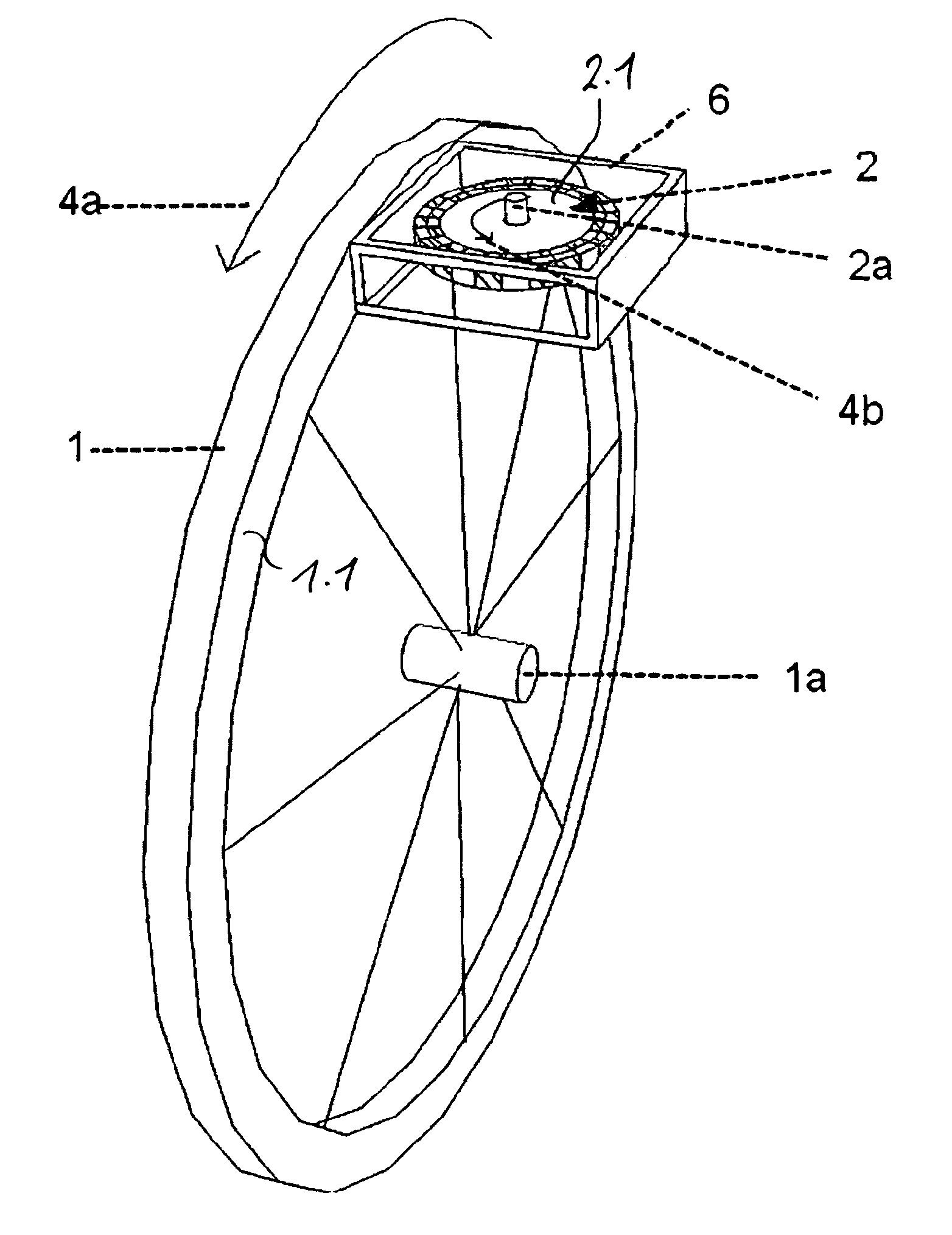
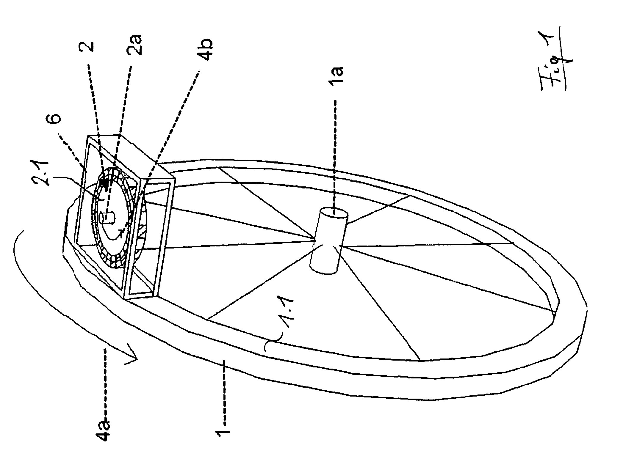
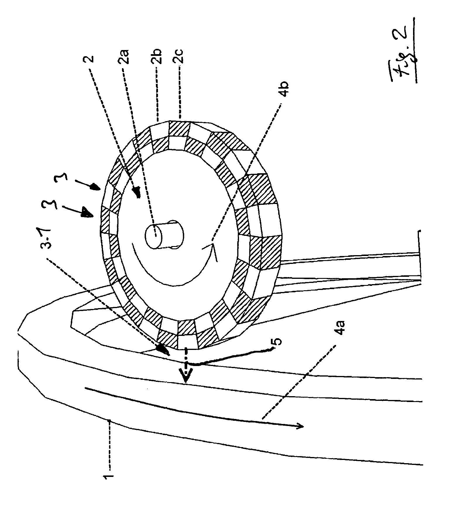
[0083]The inventive device according to FIG. 1 comprises a counter element 1, which couples with a rotatably mounted rotor element 2. For this purpose the counter element 1 is a rim formed with a lateral surface 1.1, which forms a continuous circular path. The rim 1 is conductive, for example, made of aluminium. The rotor element 2 comprises a carrier 2.1 on which a plurality of magnets is arranged peripherally which is described in more detail below. The carrier 2.1. is rotatably mounted with the magnets on an axis 2a. A rotational movement of the counter element / the rim in direction 4a causes a rotational movement of the rotor element 2 equipped with magnets in direction 4b. The rotor element 2 of this object which now acts as an eddy current magnetic gear is encapsulated entirely to the outside for example, to weathering, within one box 6. No sensitive, moving parts are in direct contact with the environment. The rotary axis inside the axis 2a, is perpendicular to a straight line...


PUM


Abstract

A device for contactless current generation, in particular bicycle dynamo, on a rotatable counter element, in particular wheel rim, with at least one movably mounted rotor element (2) having at least one magnet (3), and at least one coil (7), in the at least one winding of which a current can be induced by the magnet (3), which moves together with the rotor element (2), said current being usable to operate a consumer, wherein the rotor element (2) is movable by magnetic interaction with the counter element (1), characterized in that the rotor element (2) and the counter element (1) have different axial profiles, and, in an operative position, the rotor element (2) is designed to generate at least one magnetic field (6a, 6b) on the basis of an eddy current in the conductive counter element (1), which forms an uninterrupted circular path, in such a manner that, by means of continuous relative movement between the counter element (2) and rotor element (1), eddy current fields which are continuously opposed to one another and have oppositely polled magnetic fields (6a, 6b) to one another are induced in the counter element and the rotor element (2) is thus moved together with the counter element (1) with an eddy current gearing being formed. Furthermore, the invention relates to a vehicle lighting system and to a bicycle, each with a corresponding device for current generation.

Description

CROSS-REFERENCE TO RELATED APPLICATIONS[0001]This application is an U.S. national phase application under 35 U.S.C. §371 based upon co-pending International Application No. PCT / EP2012 / 001431 filed on Mar. 31, 2012. Additionally, this U.S. national phase application claims the benefit of priority of co-pending International Application No. PCT / EP2012 / 001431 filed on Mar. 31, 2012, German Application No. 20 2011 102 664.0 filed on Jul. 1, 2011, and German Application No. 20 2011 107 060.7 filed on Oct. 20, 2011. The entire disclosures of the prior applications are incorporated herein by reference. The international application was published on Jan. 10, 2013 under Publication No. WO 2013 / 004320 A1.BACKGROUND OF THE INVENTION[0002]1. Field of the Invention[0003]2. Description of the Prior Art[0004]The present invention relates to a device for contactless current generation, in particular bicycle dynamo, on a rotatable counter element, in particular wheel rim, with at least one movably m...

Claims


Application Information

Patent Timeline
IPC IPC(8): B60Q1/14H02K7/18H02K49/04B60Q1/00H02K21/14H02K7/11B62J6/08H02J7/34
CPCH02J7/345B60Q1/00B62J6/08H02K7/11H02K7/1846H02K21/14H02K49/04B62J6/06B62L1/00H02K1/14H02K7/18
Inventor STROTHMANN, DIRK
Owner MAGNIC INNOVATIONS
Why Eureka
Try Eureka