Sound system with individual playback zones

a sound system and playback zone technology, applied in the field of sound systems, can solve problems such as user disturbance, and achieve the effect of increasing the audibility of the second audio signal and reducing the first audio signal

Active Publication Date: 2016-01-12
HARMAN BECKER AUTOMOTIVE SYST
View PDF7 Cites 8 Cited by
  • Summary
  • Abstract
  • Description
  • Claims
  • Application Information

AI Technical Summary

Benefits of technology

[0013]Therefore, because the mixing mode may be selected based on the type information, a flexible and situation-specific mixing may be achieved.
[0019]When individually mixing based on a first mixing mode, a first signal output gain of the first audio signal may be decreased based on the loudness if compared to a second signal output gain of the second audio signal. In other words: the amount of decreasing the first signal output gain may equal a certain amount which, in turn, may depend on the loudness. Then the signal output level of the second audio signal averaged over time may be larger than the averaged signal output level of the first audio signal. Increased audibility of the second audio signal, e.g., the announcement audio signal may thus be achieved.
[0020]In particular, in the first mixing mode the second signal output gain may be equal to a reference signal output gain related to a volume setting and the first signal output gain may be decreased if compared to the reference signal output gain. This may have the effect that the averaged signal output level of the first audio signal is decreased by a certain amount if compared to the level desired by the user via the volume setting. In other words: the user may perceive the mixing of the announcement signal to the entertainment signal as an attenuation of the entertainment signal while the announcement signal is output at the signal level desired by the volume setting. Of course it may also be possible to output the announcement signal at an averaged signal output level which is, e.g., above the level desired by the volume setting. It may also be possible to set the relation between the reference signal output gain and the first and second signal output gains as a function of the determined loudness of the first audio signal.
[0023]By providing a constant signal output gain for the second audio signal below a threshold loudness, audibility of the announcements et cetera may be ensured even when the first audio signal has a very low loudness value. Furthermore, by having the signal output gain of the second audio signal larger than the signal gain of the first audio signal, the averaged signal output level of the second signal may be larger than the averaged signal output level of the first signal and therefore audibility of the announcements may be ensured at all times.
[0025]Then, for example if the type information of the second audio signal relates to navigation instructions or status indication of a telephone call, the first mixing mode may be selected for a first playback zone targeted at front seat passengers of the vehicle and the third mixing mode may be selected for a second playback zone targeted at rear seat passengers of the vehicle. Status indication of a telephone call may relate to, e.g., dialing tone, line busy signal, etc. In such a situation, distraction of the rear seat passengers may be reduced. Navigation instructions may only be relevant to the driver of a vehicle. Then by setting the second signal output gain of the second audio signal to zero for playback in the respective playback zone, distraction of rear seat passengers may be reduced.
[0028]For example, it may not be necessary to reduce the averaged signal output level of the first audio signal, e.g., an entertainment signal, for a situation of engaged park distance control. The second audio signal may be mixed on top of the first audio signal. This may reduce distraction of passengers in the vehicle.

Problems solved by technology

However, the large number of announcement signals used and present in a modern vehicle typically requires a frequent intervention of the playback of the entertainment audio signal which can cause disturbance to the users.

Method used


Image

  • Sound system with individual playback zones
  • Sound system with individual playback zones
  • Sound system with individual playback zones

Examples


Embodiment Construction

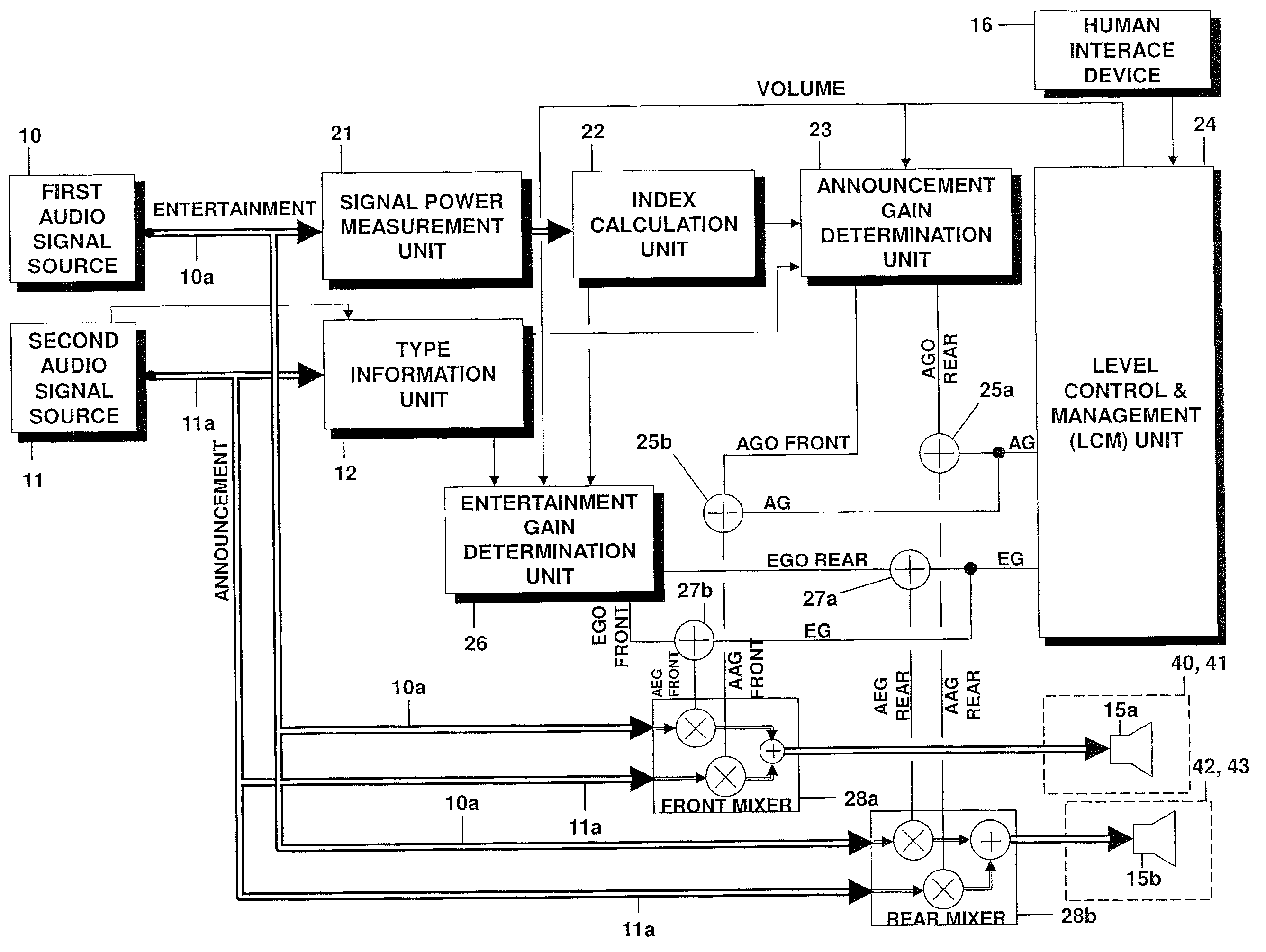
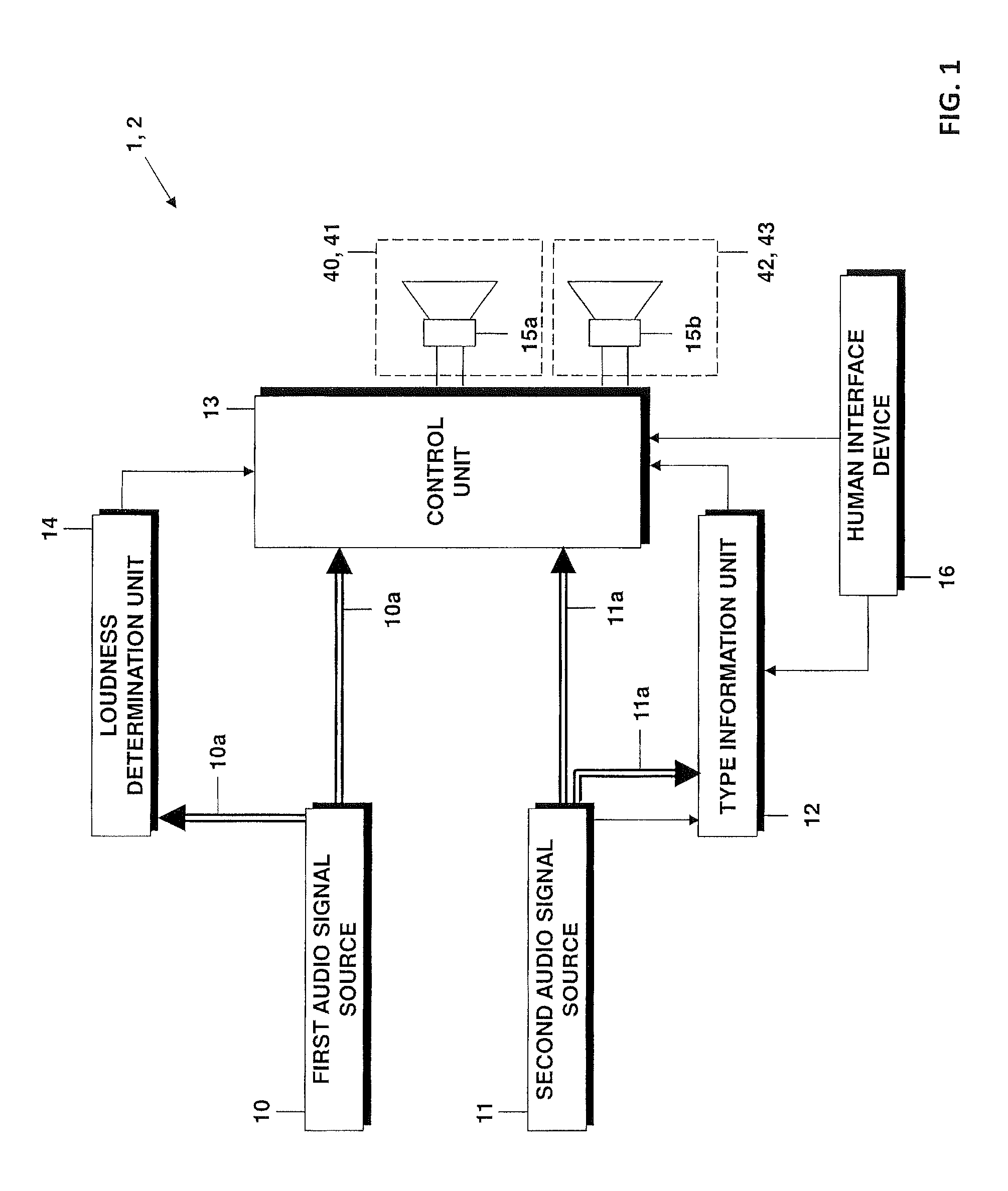
[0041]In FIG. 1, a schematic view of a sound system 2 comprising different sound sources 10, 11 is shown. The sound system 2 of FIG. 1 can be part of a multimedia system of a vehicle 1 comprising different modules such as a navigation unit, a radio receiver, a MP3 player, a CD player, etc.

[0042]The sound system 2 of FIG. 1 comprises the first audio signal source 10 in the form an entertainment audio signal source 10 and the second audio signal source 11 in the form of an announcement audio signal source 11. The entertainment audio signal source 10 outputs an entertainment audio signal 10a, the announcement audio signal source outputs an announcement audio signal 11a when needed.

[0043]Examples for the announcement audio signal 11a are announcements relating to navigation instructions, fuel level, or other status information of the vehicle 1 including park distance control sound indication or a gong. It is also possible that the announcement audio signal 11a relates to a telephone cal...


PUM


Abstract

The invention relates to a sound system in a vehicle. The sound system comprises a first audio signal source providing a first audio signal and a second audio signal source providing a second audio signal. The sound system further comprises loudness determination unit is configured for determining a loudness of the first audio signal based on a psycho-acoustic model of a human hearing and a type information unit configured for establishing type information of the second audio signal. The sound system further comprises a control unit configured for individually selecting, for each of at least two playback zones, a mixing mode depending on the type of the second audio signal, wherein the mixing modes relate to a relation between signal output gains of the first and second audio signals. The control unit is further configured for individually mixing for playback, in each of the at least two playback zones, the first audio signal and the second audio signal based on the selected mixing mode and the determined loudness. The sound system further comprises a plurality of loudspeakers addressing individually the at least two playback zones.

Description

CLAIM OF PRIORITY[0001]This patent application claims priority from EP Application No. 11 196 080.3 filed Dec. 29, 2011, which is hereby incorporated by reference.FIELD OF TECHNOLOGY[0002]This invention relates to a sound system comprising a first audio signal source and a second audio signal source and a plurality of loudspeakers addressing individually at least two playback zones and a method of mixing the first and the second audio signals individually in the at least two playback zones. The invention especially finds application in vehicles, where multimedia systems are used comprising a navigation module and an audio module such as a radio receiver, compact disc unit, etc.RELATED ART[0003]Motor vehicle navigation systems as such have been known for a relatively long time and are increasingly offered in new vehicles or retrofitting purposes. In this context, the navigation systems are used to guide the driver of the vehicle from the present location to a destination location. In...

Claims


Application Information

Patent Timeline
Patent Type & Authority Patents(United States)
IPC IPC(8): H03G3/00H03G3/20H04R3/12H04S7/00H04R5/02
CPCH03G3/20H04R3/12H04S7/30H04R2499/13
Inventor HESS, WOLFGANGWAGNER, STEFFEN
Owner HARMAN BECKER AUTOMOTIVE SYST
Why Eureka
Try Eureka