
Variable volume combustion chamber system

a combustion chamber and variable volume technology, applied in the direction of machines/engines, non-mechanical valves, oscillatory slide valves, etc., can solve problems such as combustion fluctuations and misfires

Inactive Publication Date: 2016-01-19
MANKE DONALD W
View PDF24 Cites 12 Cited by
  • Summary
  • Abstract
  • Description
  • Claims
  • Application Information

AI Technical Summary

Benefits of technology

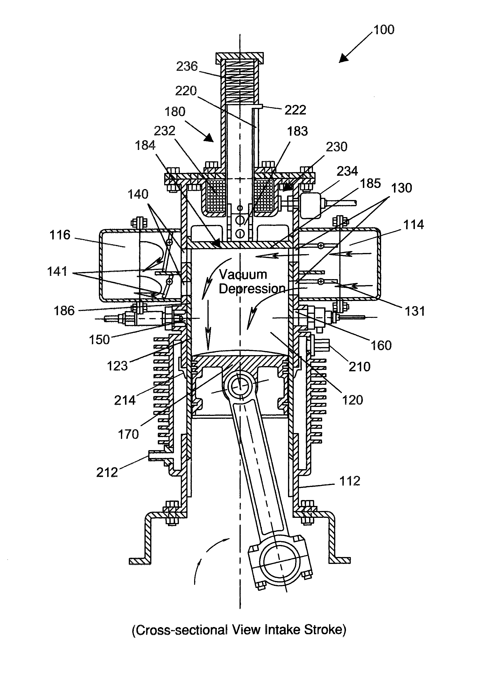
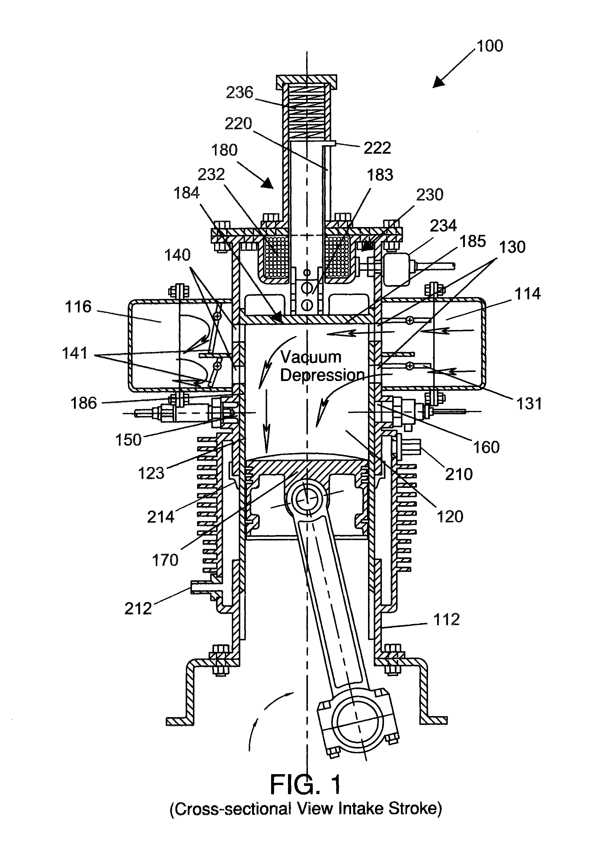
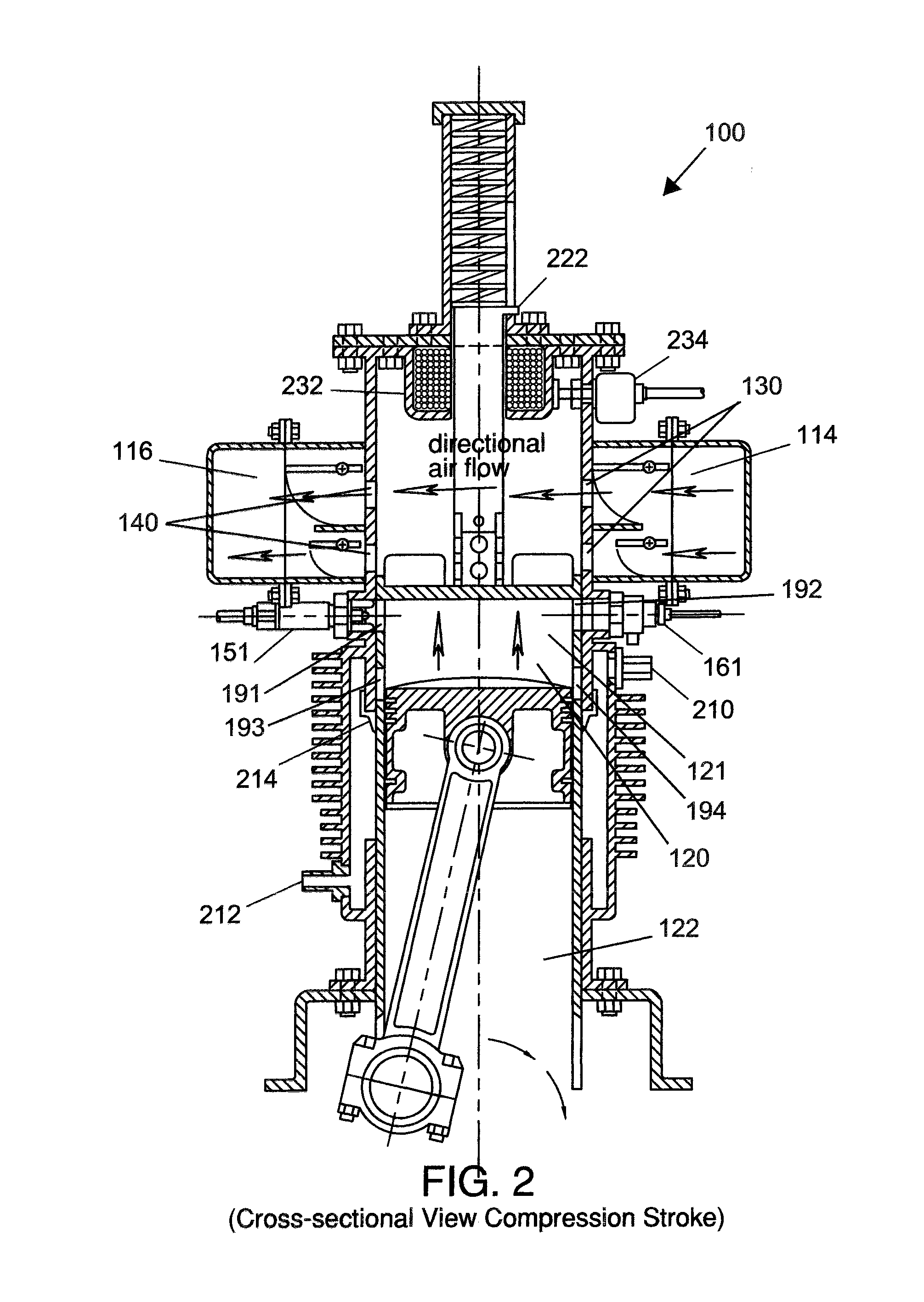
The present invention is related to a variable volume combustion chamber for an internal combustion engine. The system includes an engine with a cylindrical combustion chamber, which has open chamber top and bottom. The intake port is connected to an intake manifold, the intake valve controls airflow into the combustion chamber, and the exhaust port is connected to an exhaust manifold, the exhaust valve controls exhaust gas flow. The ignition plug port is located between the exhaust port and the chamber bottom and the fuel injection port is tangential to the combustion chamber. An adjustable volume head assembly is located on the chamber top and can be controlled by a solenoid. The cylindrical head and sleeve component comprises a planar head and a hollow cylindrical sleeve with two ports. The positioning shaft is perpendicularly affixed to the cylindrical head and sleeve component and can be moved via actuation of the solenoid. The invention enables precise control over the volume of the combustion chamber and optimizes engine performance.

Problems solved by technology

Lean charges lead to reduced CO and HC emissions, but they may also produce misfires and combustion fluctuations.

Method used


Image

  • Variable volume combustion chamber system
  • Variable volume combustion chamber system
  • Variable volume combustion chamber system

Examples


Embodiment Construction

[0041]Following is a list of elements corresponding to a particular element referred to herein:[0042]100 Variable volume combustion chamber system[0043]112 Engine side wall[0044]114 Intake manifold[0045]116 Exhaust manifold[0046]120 Combustion chamber[0047]121 Chamber top[0048]122 Chamber bottom[0049]123 Chamber side wall[0050]130 Intake port[0051]131 Intake valve[0052]140 Exhaust port[0053]141 Exhaust valve[0054]150 Ignition plug port[0055]151 Spark plug[0056]160 Fuel injection port[0057]161 Fuel injector[0058]170 Piston[0059]180 Head assembly[0060]183 Positioning shaft[0061]184 Head and sleeve component[0062]185 Head[0063]186 Sleeve[0064]191 First port[0065]192 Second port[0066]193 Third port[0067]194 Fourth port[0068]210 Coolant inlet[0069]212 Coolant outlet[0070]214 Wiper ring[0071]220 Cylinder track slot[0072]222 Cylinder track guide and limit stop pin[0073]230 Solenoid[0074]232 Electro-magnet[0075]234 Electro-magnet module control[0076]236 Spring

[0077]Referring now to FIGS. 1-...


PUM


Abstract

A variable volume combustion chamber system for a four-cycle internal combustion engine features an engine having a cylindrical combustion chamber inside. An intake port and an exhaust port are located on a chamber side wall. An ignition plug port and a tangentially-mounted fuel injection port are also located on the chamber side wall. A cylindrical piston is pivotally located on a connecting rod in the combustion chamber. The system features an adjustable volume head assembly located on a chamber top featuring a solenoid connected to a cylindrical head and sleeve component via a positioning shaft. The cylindrical head and sleeve component adjustably extends through the chamber top into the combustion chamber and is movable via actuation of the solenoid.

Description

CROSS REFERENCE[0001]This application is a non-provisional of and claims priority to U.S. Provisional Patent Application No. 62 / 004,056, filed May 28, 2014, the specification(s) of which is / are incorporated herein in their entirety by reference.FIELD OF THE INVENTION[0002]The present invention relates to internal combustion engines, or more specifically, internal combustion engines having a variable volume combustion chamber with integral sleeve valve ports.BACKGROUND OF THE INVENTION[0003]It has long been known that increasing the compression ratio of an internal combustion engine increases its thermodynamic efficiency. It has also been long known that if the geometric volume ratio remains constant (i.e., a fixed volume combustion chamber), the pressure ratio is decreased, resulting in a mixture in the combustion chamber whose pressure is below that obtained at full throttle. One approach to restoring the full pre-combustion pressure (or achieving the desired pressure ratio) is to ...

Claims


Application Information

Patent Timeline
Patent Type & Authority Patents(United States)
IPC IPC(8): F02B75/04F02D15/04F01L5/06F01P1/02
CPCF02B75/042F02D15/04F01L5/06F01P1/02F02D2700/03F01P2001/026F01L7/02F01L7/04F01L2810/01F01L2810/02F02B23/104F02B25/08F02B2023/102F02B2023/108Y02T10/12F01L2009/2103F01L9/20
Inventor MANKE, DONALD, W.
Owner MANKE DONALD W
Learn More