Planet roller speed changer
a technology of planet roller and speed changer, which is applied in the direction of belt/chain/gearing, friction gearing, belt/chain/gearing, etc., can solve the problem of large rotational fluctuations in the planet roller speed changer, and achieve the effect of high degree of rotation accuracy
- Summary
- Abstract
- Description
- Claims
- Application Information
AI Technical Summary
Benefits of technology
Problems solved by technology
Method used
Image

Examples
first embodiment
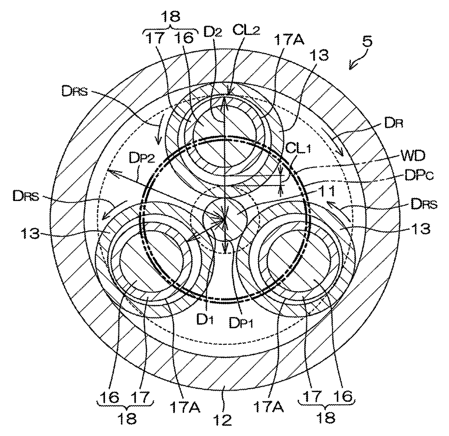
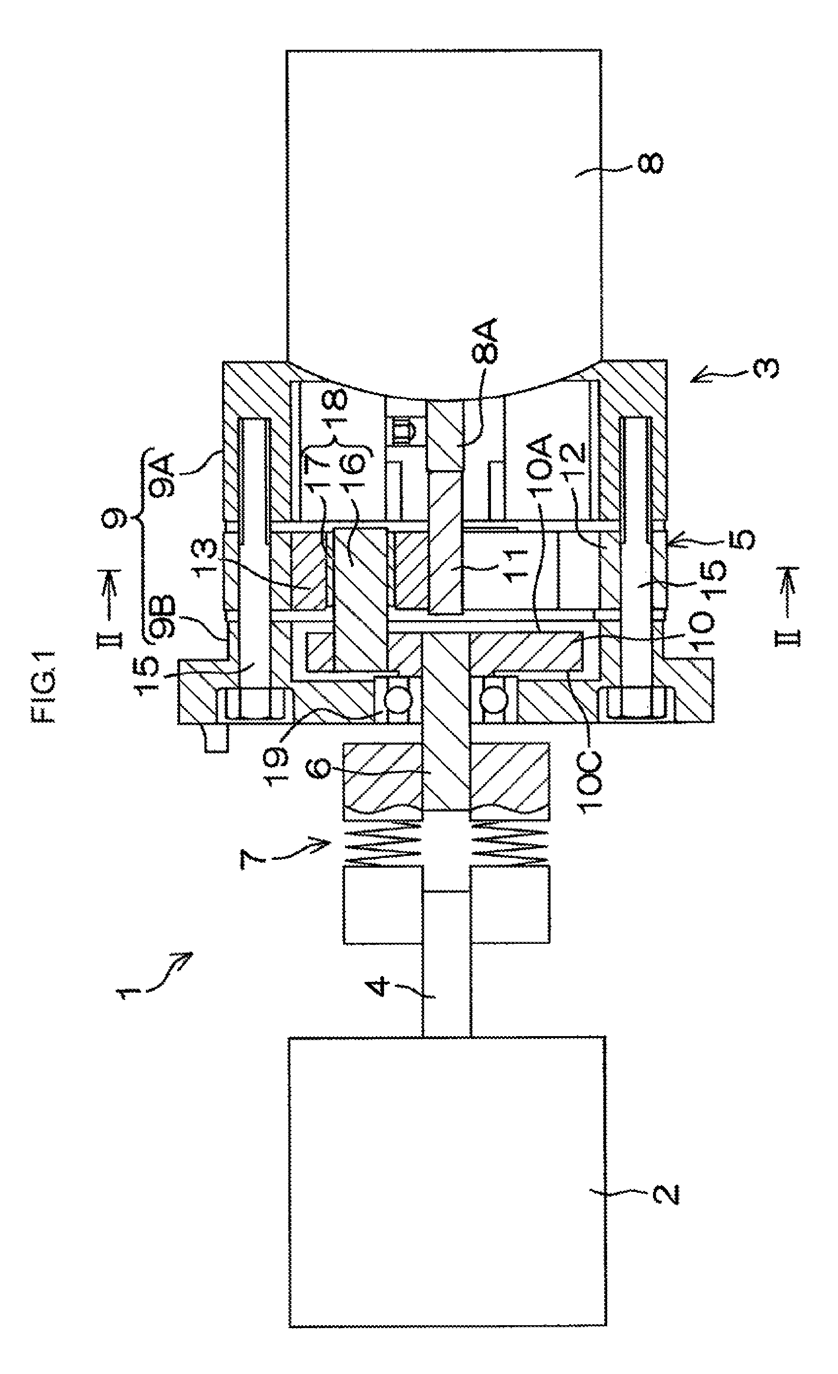
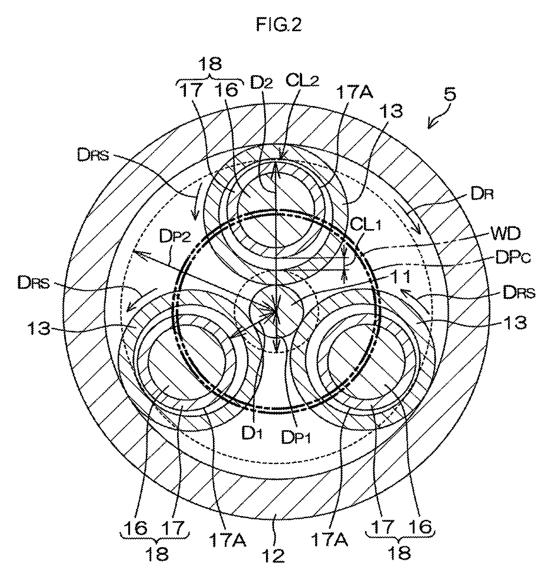
[0018]Hereinafter, example embodiments of the invention will be described in detail with reference to the accompanying drawings. FIG. 1 is a view illustrating the schematic configuration of a power transmitting device 1 of an image forming apparatus such as a printer, in which a planet roller speed changer 5 according to the invention is mounted. FIG. 2 is a cross-sectional view taken along the line II-II in FIG. 1. The power transmitting device 1 of the image forming apparatus includes a body 2 to be driven (hereinafter, referred to as “driven body 2”), a planet roller speed changing unit 3, and a coupling 7. The driven body 2 is driven to be rotated by the planet roller speed changing unit 3. The coupling 7 couples a driven body input shaft 4 of the driven body 2 and an output shaft 6 of the planet roller speed changer 5 to each other. In the power transmitting device 1, the planet roller speed changing unit 3 is mounted transversely so that the output shaft 6 extends horizontally...
second embodiment
[0036]In the planet roller speed changer 105, a pitch circle diameter DPC1 of the carrier 10 is set substantially equal to a value WD1 obtained by doubling the inter-axis distance between the input shaft 11 and each planet roller 13. In this case, the clearance between the shaft portion 18 and the planet roller 13 on the input shaft 11 side is substantially equal to the clearance between the shaft portion 18 and the planet roller 13 on the stationary ring 12 side. In the second embodiment, each shaft portion 18 includes a bushing 117 in place of the bushing 17. The bushing 117 has a generally cylindrical shape. The bushing 117 has an outer peripheral face 117A having a cylindrical face. Each of the outer peripheral faces 117A has a cut portion 111 formed of a flat face, and the radius of the bushing 117 at the cut portion 111 is shorter than the radius of the bushing 117 at the other portion than the cut portion 111. The cut portion 111 is located at a part of the bushing 117 in the...
PUM
 Abstract
Description
Claims
Application Information
 - R&D
- Intellectual Property
- Life Sciences
- Materials
- Tech Scout
- Unparalleled Data Quality
- Higher Quality Content
- 60% Fewer Hallucinations
Browse by: Latest US Patents, China's latest patents, Technical Efficacy Thesaurus, Application Domain, Technology Topic, Popular Technical Reports.
© 2025 PatSnap. All rights reserved.Legal|Privacy policy|Modern Slavery Act Transparency Statement|Sitemap|About US| Contact US: help@patsnap.com