Safety fall arrestor and wind lock for vertical lift doors

a safety fall arrestor and vertical lift door technology, which is applied in the direction of wing operation mechanisms, door/window fittings, constructions, etc., can solve the problems of significant damage to the vertical lift door or the building structure, significant wear of the lift cable and the lift mechanism, and injury to individuals or damage to goods in the vicinity, so as to improve the reliability of activation and minimize structural damage

Inactive Publication Date: 2016-01-26
KAOUNAS JOHN
View PDF9 Cites 9 Cited by
  • Summary
  • Abstract
  • Description
  • Claims
  • Application Information

AI Technical Summary

Benefits of technology

[0010]Accordingly, it is an object of the invention to provide a fall arrestor with improved reliability in activation and binding to a vertical rail and minimizing structural damage while preventing movement of the vertical lift door in a catastrophic failure.

Problems solved by technology

The heavy weight of the door and its inherent exposure to adverse environmental conditions lead to substantial lift cable and lift mechanism wear.
In the event of a catastrophic failure occurring as a result of a break in the lift cable or failure of the lift mechanism, significant damage to the vertical lift door or the building structure may occur, as well as possible injury to individuals or damage to goods in the vicinity of the failed door.
However, the latching dogs extending in opposite directions from each other against the opposed sides of the U-shaped guide bar may fail to provide a reliably strong binding effect in the event of a catastrophic failure of the cable or cable lift apparatus.
The forces applied by the dogs to opposing sides of the guide rail may result in deformation of the U-shaped guide bar and significant structural damage to the vertical doorframe.
Due to the infrequent activation of the biasing mechanism and its exposure to adverse environmental conditions, the system is prone to corrosion and contamination preventing reliable activation and binding to the guide rail in the event of a catastrophic failure.
Furthermore, a direct drive connection such as a torsion spring mounted on an axle which the spring must rotate in a catastrophic failure requires greater torque than a compression spring utilizing a cam mechanism to pivot the latching dogs.

Method used


Image

  • Safety fall arrestor and wind lock for vertical lift doors
  • Safety fall arrestor and wind lock for vertical lift doors
  • Safety fall arrestor and wind lock for vertical lift doors

Examples


Embodiment Construction

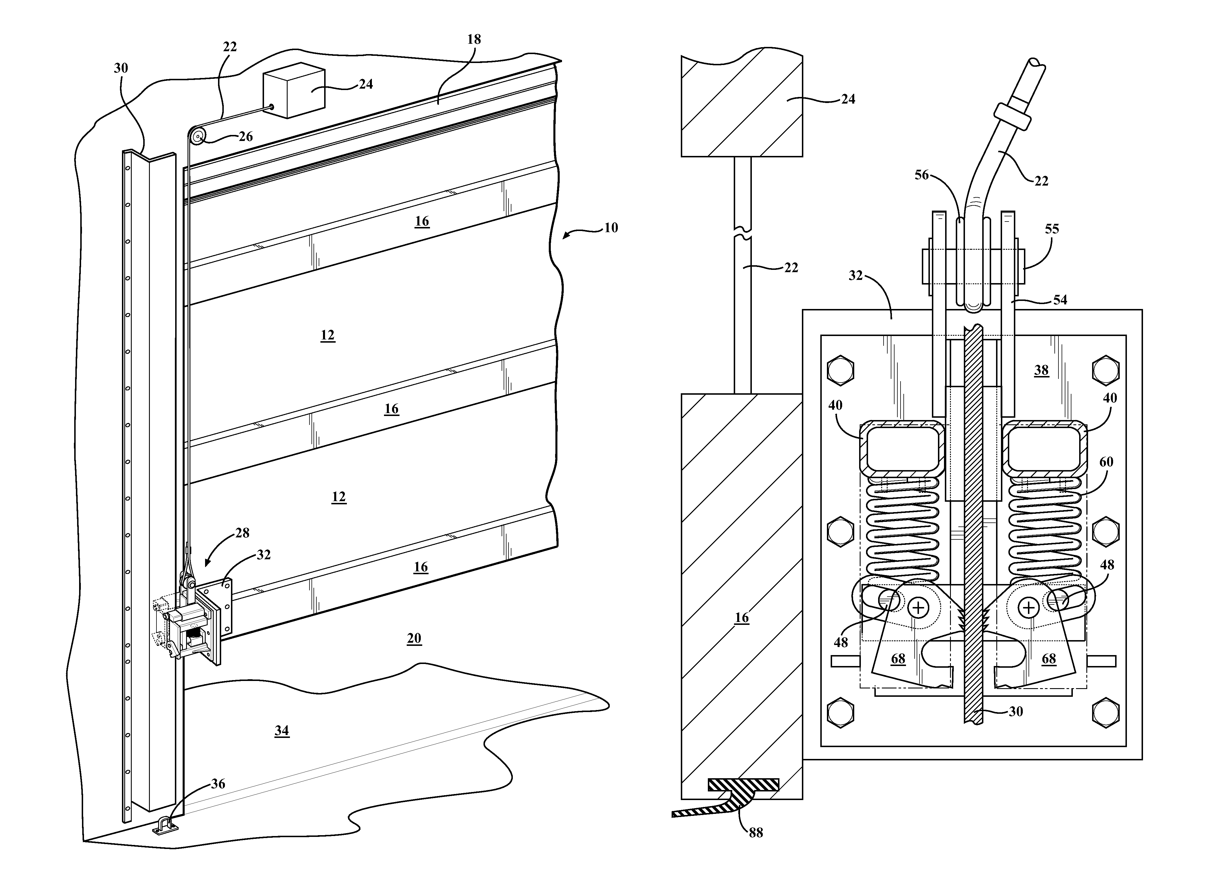
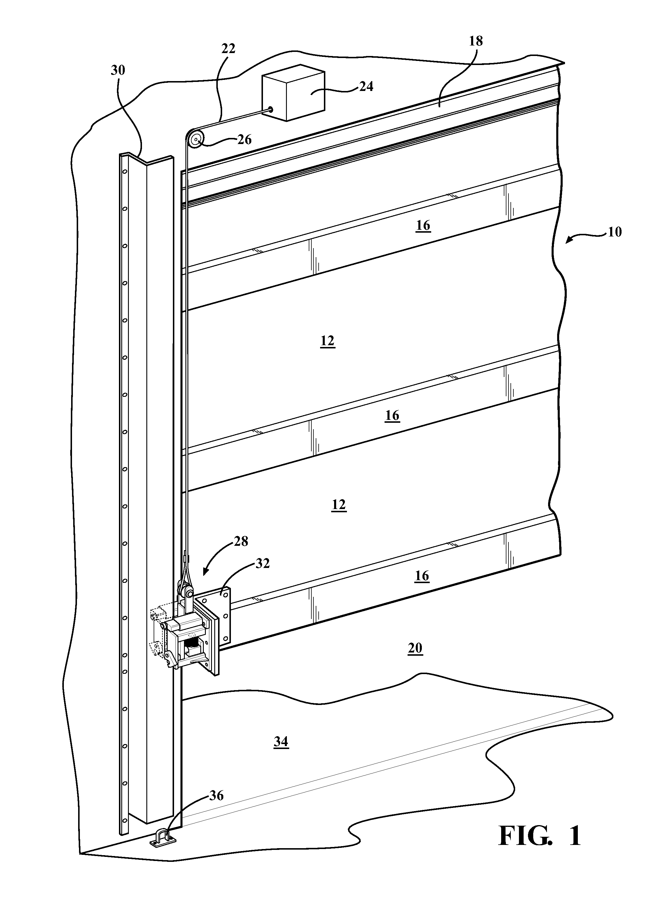
[0020]A preferred embodiment of the invention, illustrated generally in FIG. 1, is used in connection with a conventional, multi-panel vertical lift door. The door 10 has a number of panels 12 arranged one above the other and connected by horizontal hinge sections 16. The top panel is supported by a bracket 18 extending horizontally across the top of an opening 20 to be closed by the door.

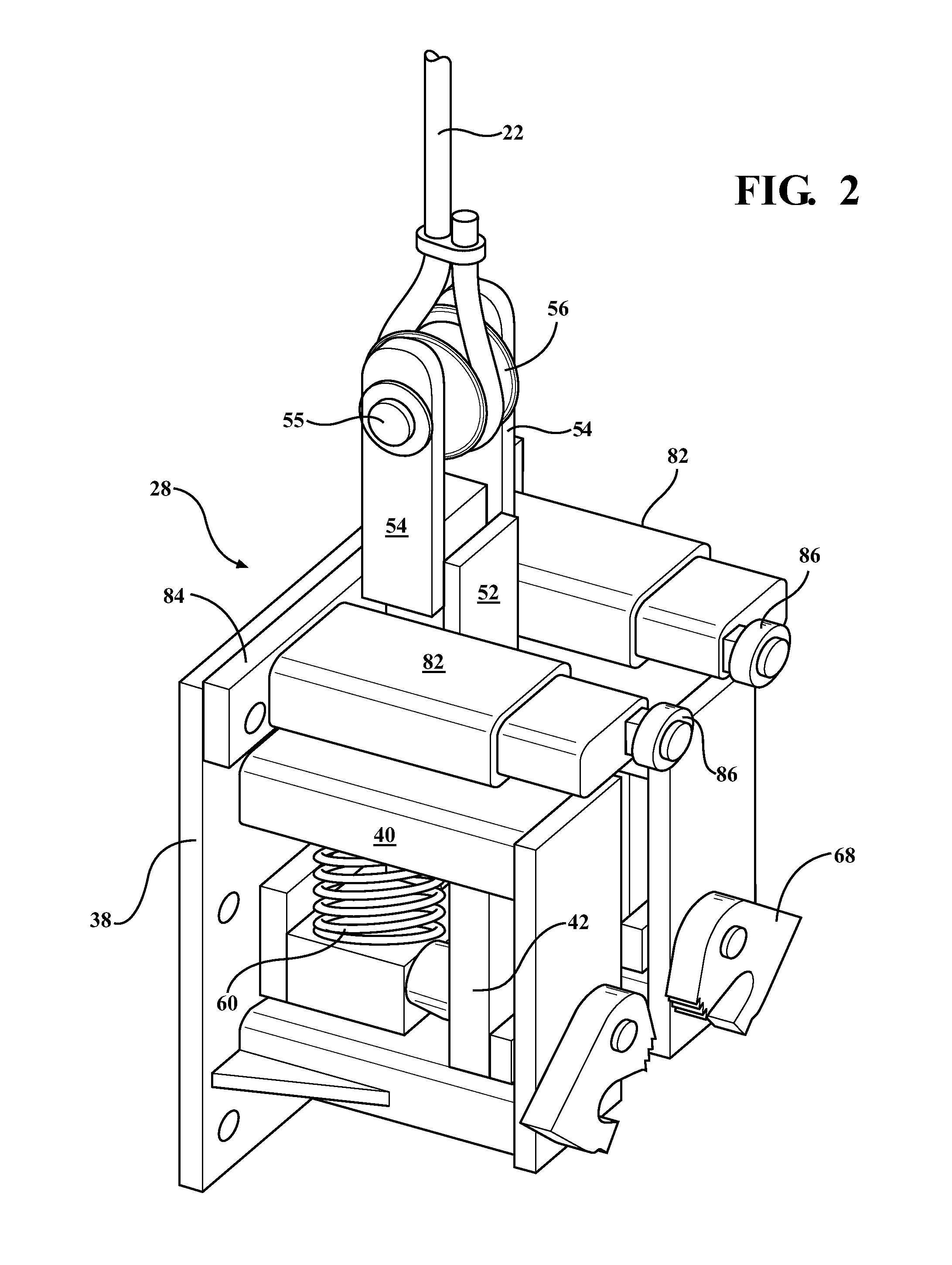
[0021]The door may be lifted and lowered by a cable 22 connected to a power drive 24. The cable can take the form of any flexible tension member including a wire, cable, rope, chain, or strap. The cable is arrayed over a pulley 26 rotatably supported on one wall of the building and extends downwardly to a fall arrestor, generally indicated at 28, which is fixed to the lowest bar 16 of the door 10. The drive 24 acts to raise and lower the door by retracting or lowering the cable.

[0022]A vertically extending L-shaped guide rail 30 is secured to the wall of the building alongside the edge of the door ...


PUM


Abstract

A fall arrestor for use with a vertical lift door includes a pair of latching dogs selectively pivoted into and out of contact with a vertical rail by cam members and a compression mechanism actuated by a change in tension between a lift cable and the vertical lift door. The fall arrestor further includes a ground locking system for locking the door when the vertical lift door is completely closed. The fall arrestor is capable of preventing of free fall of the vertical lift door in a catastrophic failure of a lift mechanism or the lift cable.

Description

FIELD OF THE INVENTION[0001]The invention relates to a safety fall arrestor and securing device for vertical lift doors. More specifically, the invention relates to such a device for use on vertical lift doors for improving their safety performance by preventing free fall of the vertical lift door in the event of a catastrophic failure of the lifting mechanism and securing the vertical lift door in closed position.BACKGROUND OF THE INVENTION[0002]Vertical lift doors are used in a variety of industries where structures require large doorways. For example: aircraft hangars require hangar doors large enough for an aircraft to pass through, factories often require large doorways for receiving materials and equipment as well as the exiting of finished products.[0003]The type of vertical lift door for such applications may vary based on specific industry requirements, structural support capacity, or the intended environment. Generally, two types of vertical lift doors are common. First, a...

Claims


Application Information

Patent Timeline
Patent Type & Authority Patents(United States)
IPC IPC(8): E05D13/00E05D15/24
CPCE05F15/686E05D13/006E05D15/242
Inventor KAOUNAS, JOHN
Owner KAOUNAS JOHN
Why Eureka
Try Eureka