
Fracture fatigue entropy determination

a fatigue load and fracture technology, applied in the field of material science and engineering, can solve the problems of crack formation in all structures and machinery components undergoing fatigue load, reduced strength of structure or component, and increased growth of subsequent growth

Active Publication Date: 2016-01-26
BOARD OF SUPERVISORS OF LOUISIANA STATE UNIV & AGRI & MECHANICAL COLLEGE
View PDF0 Cites 10 Cited by
  • Summary
  • Abstract
  • Description
  • Claims
  • Application Information

AI Technical Summary

Benefits of technology

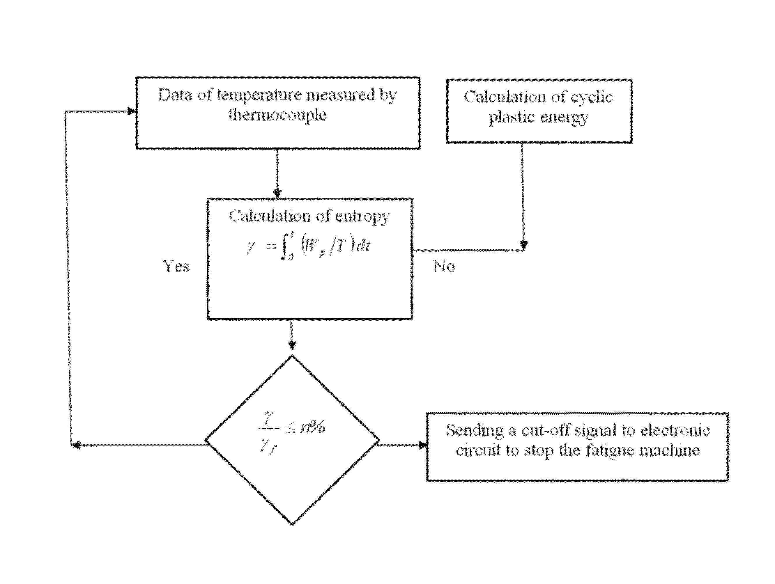
The present invention provides a method for determining the fracture fatigue entropy (FFE) of a material using a controlled lab setting and monitoring the temperature of the material during cyclical loading. The FFE is the total accumulated entropy at the point of failure. The invention also includes monitoring the accumulated entropy over time and generating an appropriate signal when the accumulated entropy reaches a predetermined set point, which can automatically shut down the machine or alert an operator. The invention also includes a fatigue failure prevention unit that calculates the accumulated entropy over time and generates appropriate signals to shut down or warn the operator of the fatigue failure risk. The technical effects of the invention are the prevention of fatigue failure and the early detection of potential failures, which can save time, money, and reduce downtime.

Problems solved by technology

All structures and machinery components undergoing fatigue loading are prone to crack formation and its subsequent growth that increases with time.
When a crack is formed, the strength of the structure or the component is decreased and can no longer function in the intended manner for which it was designed for.
Moreover, the residual strength of the structure decreases progressively with increasing crack size.
Eventually, after a certain time the residual strength becomes so low that the structure fails.
On the contrary, in the case of cyclic loading, where the stress is one of fatigue, the material arrives at the condition of local yielding (micro-plasticization) and a micro-crack is generated.
Hence, the repeated application of the stress leads to the crack propagation until, eventually, the condition of failure is reached and the specimen breaks.
In the high-cycle regime, plastic strains are usually quite small and the Wp approach becomes computationally unreliable.
Disorder in systems that undergo degradation continues to increase until a critical stage when failure occurs.
Simultaneously with the rise in disorder, entropy monotonically increases.

Method used


Image

  • Fracture fatigue entropy determination
  • Fracture fatigue entropy determination
  • Fracture fatigue entropy determination

Examples


Embodiment Construction

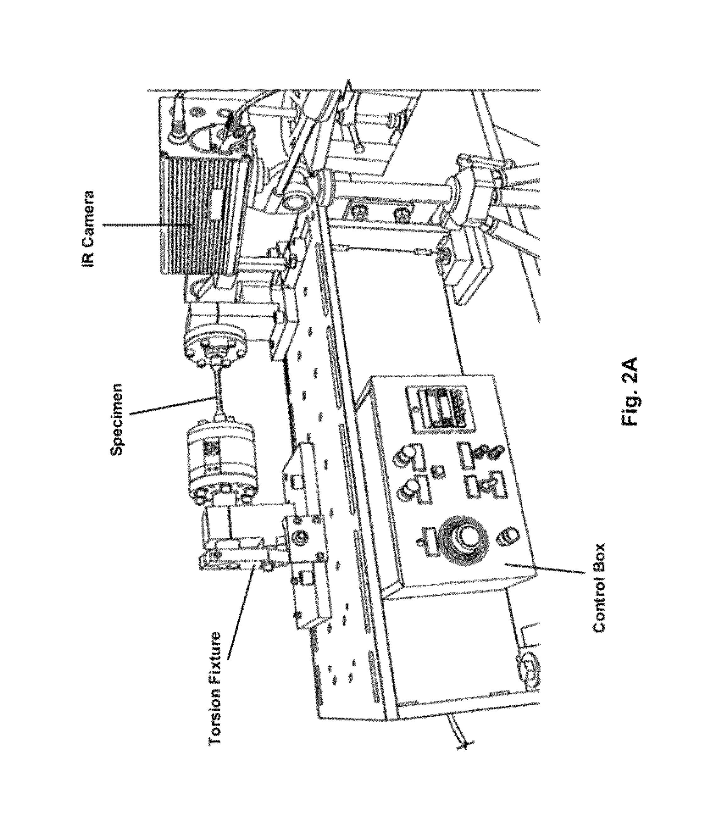
[0029]Fatigue tests were performed to evaluate the method of the present invention. Three different stress states examined are: completely reversed bending, completely reversed torsion and tension-compression loads. Tests were conducted with Aluminum 6061-T6 and Stainless Steel 304 specimens. The testing apparatus used is a compact, bench-mounted unit with a variable-speed motor, variable throw crank connected to the reciprocating platen, with a failure cut-off circuit in a control box, and a cycle counter. The variable throw crank is infinitely adjustable from 0 to 50.8 mm to provide different levels of stress amplitude. The same fatigue apparatus is used for applying torsion, bending and tension-compression loads using appropriate fixture.

[0030]FIG. 2 shows a schematic of the experimental setup used for torsion tests. The torsional fatigue tests are made using a round bar specimen clamped at both ends and rotationally oscillated at one of the ends via a crank with specified amplit...


PUM


Abstract

A method and apparatus are disclosed for approximating in real time the fracture fatigue entropy (FFE) of a metallic object subjected to cyclic loading. Such objects experience fatigue, which can lead to failure after a number of loading cycles. The disclosed invention allows for real time monitoring of the entropy increase in a metallic object under cyclic loading, and allows for removing the object from service before fatigue fracture occurs. Through use of the present invention, users may keep metallic objects in service for longer periods, because such objects may be safely taken closer to the fatigue fracture point. The invention therefore can effectively extend the useful life of many critical components and reduce downtime resulting from repair or premature replacement.

Description

CROSS-REFERENCE TO RELATED APPLICATION[0001]The benefit of the Oct. 5, 2009 filing date of provisional patent application 61 / 248,522 is claimed under 35 U.S.C. §119 (e).FIELD OF THE INVENTION[0002]The invention relates to materials science and engineering, and in particular to the monitoring the service life of a metallic structure exposed to cyclic loading.BACKGROUND OF THE INVENTION[0003]All structures and machinery components undergoing fatigue loading are prone to crack formation and its subsequent growth that increases with time. When a crack is formed, the strength of the structure or the component is decreased and can no longer function in the intended manner for which it was designed for. Moreover, the residual strength of the structure decreases progressively with increasing crack size. Eventually, after a certain time the residual strength becomes so low that the structure fails. It is, therefore, of paramount importance to be able to predict accurately and in real time th...

Claims


Application Information

Patent Timeline
Patent Type & Authority Patents(United States)
IPC IPC(8): G01N3/32C22C38/00C22C21/00
CPCG01N3/32C22C38/00C22C21/00G01N2203/0005G01N2203/0069G01N2203/0073
Inventor KHONSARI, MICHAEL M.ABADI, MEHDI NADERIDAREHBIDI, MEHDI AMIRI
Owner BOARD OF SUPERVISORS OF LOUISIANA STATE UNIV & AGRI & MECHANICAL COLLEGE
Learn More