Method and apparatus for isolating a location of a fault in a passive optical network

a technology of optical network and fault location, applied in the direction of electrical equipment, transmission monitoring, transmission monitoring/testing/fault measurement system, etc., can solve the problems of increased maintenance and operation costs, limited number of oscs used,

Inactive Publication Date: 2009-05-21
TELLABS PETALUMA
View PDF11 Cites 79 Cited by
  • Summary
  • Abstract
  • Description
  • Claims
  • Application Information

AI Technical Summary

Problems solved by technology

A limited number of OSCs may be used because optical signal power drops each time the signal is split.
The complexity of a multipoint PON architecture, together with a system operator's interest in avoiding customer service interruptions, has increased difficulty of diagnosing and troubleshooting network problems, resulting in increased maintenance and operation costs.

Method used


Image

  • Method and apparatus for isolating a location of a fault in a passive optical network
  • Method and apparatus for isolating a location of a fault in a passive optical network
  • Method and apparatus for isolating a location of a fault in a passive optical network

Examples


Embodiment Construction

[0017]A description of example embodiments of the invention follows.

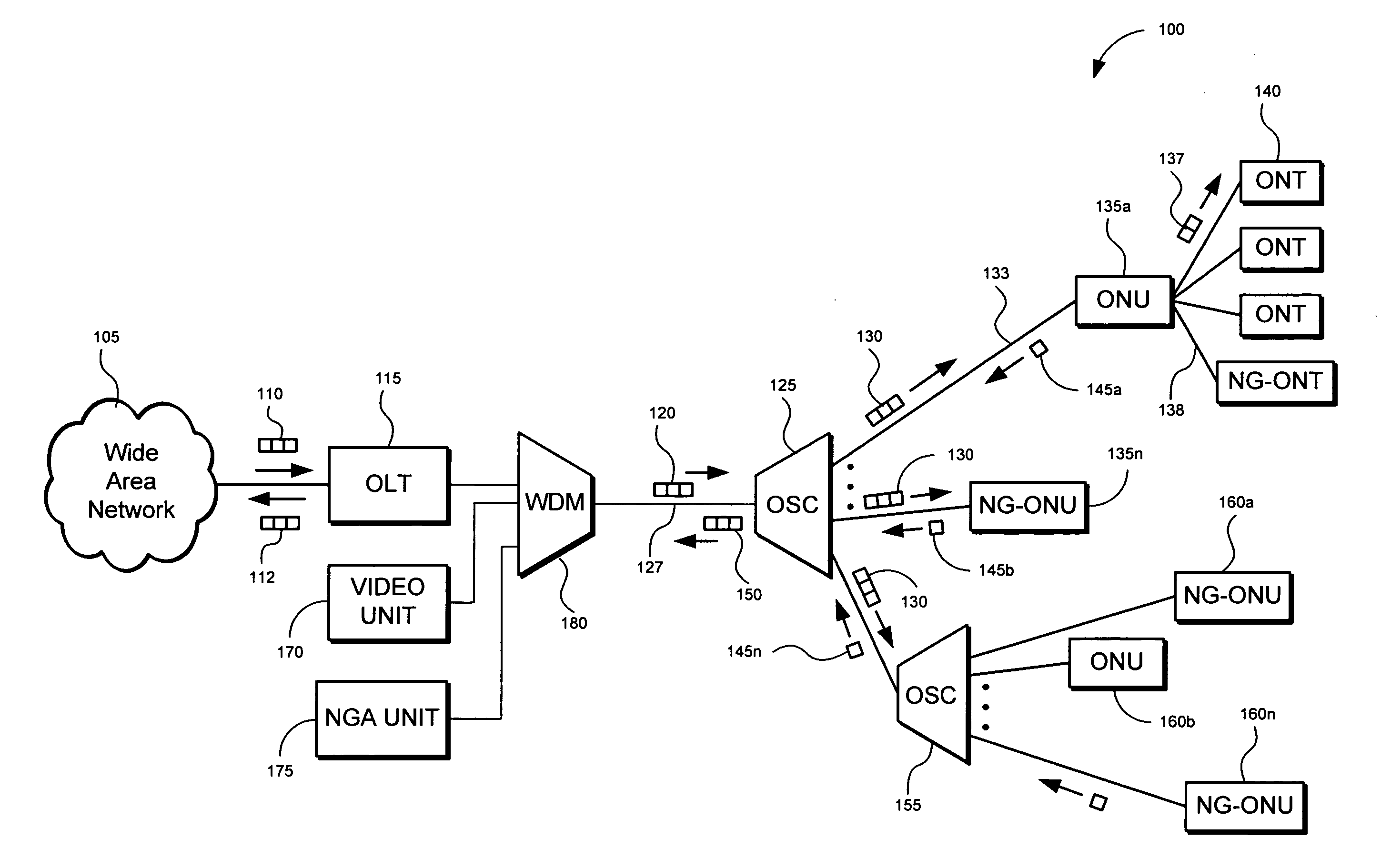
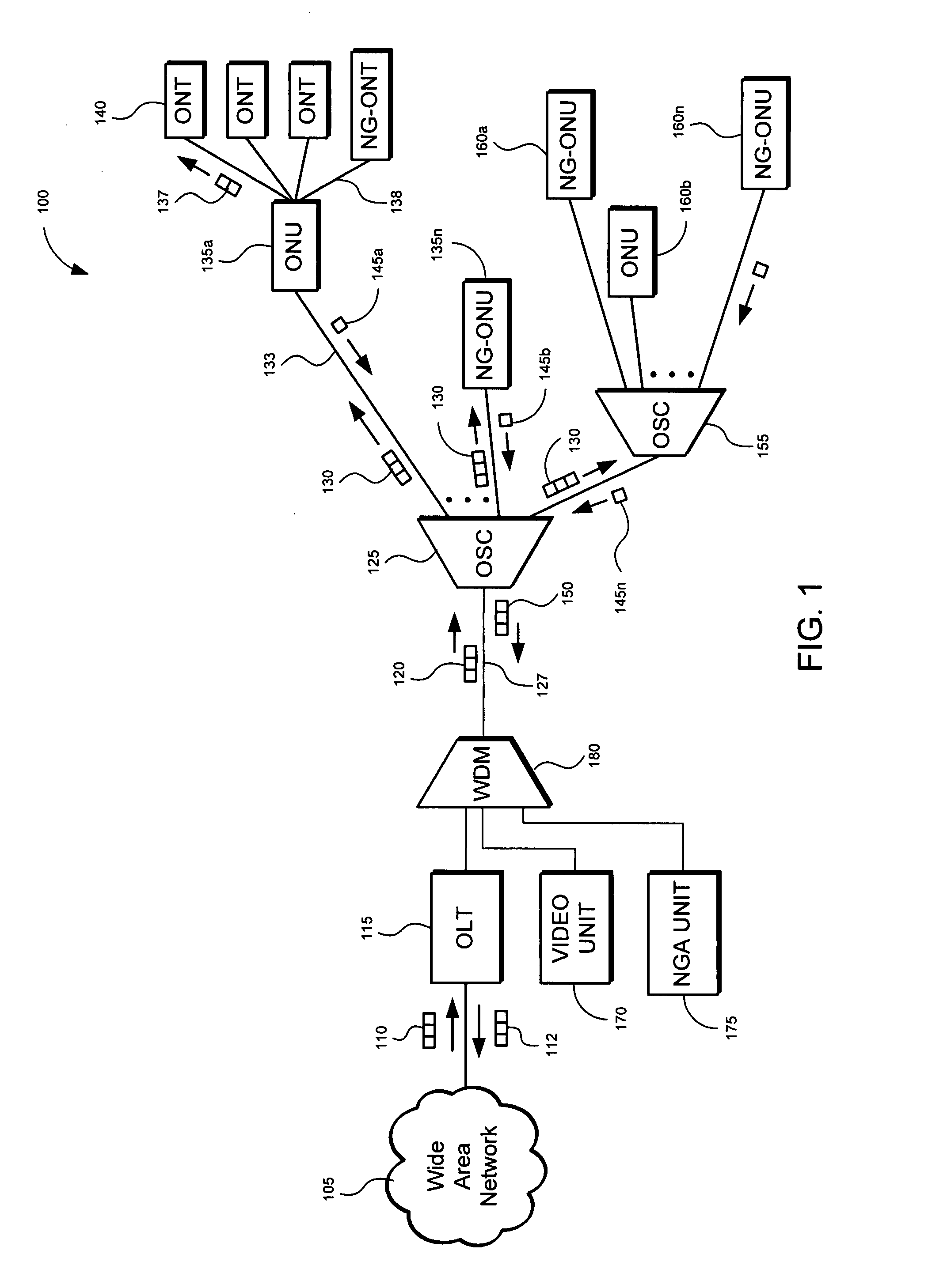
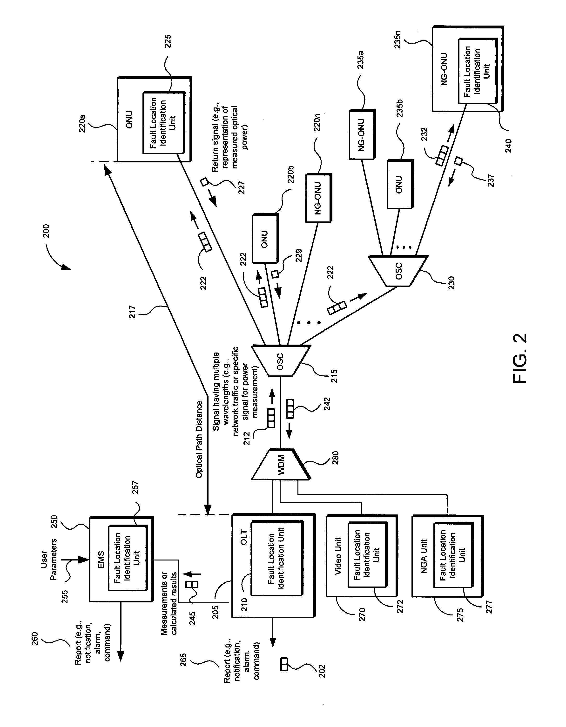
[0018]Early implementations of optical networks were deployed as point-to-point networks. With single end nodes, it is relatively easy to determine operating characteristics of the optical link, such as excess optical signal power loss. Troubleshooting and isolating the location of a fault in point-to-point optical networks is also a relatively straightforward process as there are only two network nodes and one or two communication paths. As service demands have increased, network providers have begun deploying point-to-multipoint passive optical network (PON) architectures.

[0019]The PON architecture allows a service provider to serve multiple users with less equipment and fiber as compared with equivalent point-to-point architectures. Examples include asynchronous transfer mode (ATM) PONs (APON), broadband PONs (BPON), and more recently Ethernet PONs (EPON), as described in the Institute of Electrical and Electroni...


PUM


Abstract

A method and apparatus of isolating a location of a fault in an optical network may include using communications traffic signals and network nodes to determine excess power losses without interrupting service or requiring additional external test equipment. A transmit optical network node is configured to measure the transmit power of multiple wavelengths of a transmitted optical signal. A receive optical network node is configured to measure the receive power of the same multiple wavelengths. Power differentials of the transmit and receive optical power for each wavelength may be calculated. Optical power losses as a function of the optical path distance between the transmit and receive optical network nodes my be determined. The data may be used to isolate the location of a fault in a passive optical network based on the differences between the optical power losses of the multiple wavelengths thereby reducing troubleshooting time and network downtime.

Description

BACKGROUND OF THE INVENTION[0001]A passive optical network (PON) uses optical fiber links to communicate data, video, or audio (herein collectively “data”) between network nodes. As demand for communication services has increased, system operators have increasingly deployed point-to-multipoint PONs. Within PONs, components such as optical splitter / combiners (OSC) passively split an optical signal into identical power reduced copies, allowing a single fiber connection to be shared among multiple users. A limited number of OSCs may be used because optical signal power drops each time the signal is split. Thus, a typical PON may use one OSC or perhaps cascade two OSCs. Using such an architecture, point-to-multipoint PONs allow a service provider to serve more customers with less equipment, thereby decreasing equipment cost on a per user basis.[0002]In a PON, data embedded in a light signal generated by, for example, a laser diode, flows downstream from a transmitting network node, such...

Claims


Application Information

Patent Timeline
Patent Type & Authority Applications(United States)
IPC IPC(8): H04B10/08H04B17/00
CPCH04B10/0793H04J14/0221H04J14/0227H04J14/0282H04J14/0246H04J14/025H04J14/0252H04J14/0232H04J14/0247
Inventor ORON, MOSHE
Owner TELLABS PETALUMA
Why Eureka
Try Eureka