
Systems and methods for implementing S/SSTDR measurements

a technology of s/sstdr and measurement method, applied in the direction of resisting/reacting/inhibiting, fault location, pulse reflection method, etc., can solve the problem of reducing the overall time necessary for running tests, and achieve the effect of improving s/sstdr measurement resolution and accuracy, reducing overall time necessary, and improving resolution

Active Publication Date: 2016-01-26
UNIV OF UTAH RES FOUND
View PDF7 Cites 138 Cited by
  • Summary
  • Abstract
  • Description
  • Claims
  • Application Information

AI Technical Summary

Benefits of technology

This patent describes methods and systems for testing complex systems using multiple test signals simultaneously, while compensating for interference and bandwidth restrictions. This multi-port testing can decrease the time required to run tests and allows for simultaneous analysis of the system from multiple test points, which may be useful for testing intermittent faults or function from multiple directions / points. Additionally, the patent includes techniques to improve the accuracy and resolution of the testing results, such as utilizing a pseudo noise code and curve fitting algorithms, statistical evaluation, and longer PN codes or averaging over multiple PN codes to reduce measurement noise. The patent also discusses the use of circuit modeling techniques to predict behavior and failure likelihood of a circuit under test, which can be useful for analyzing entire circuits and making failure predictions.

Problems solved by technology

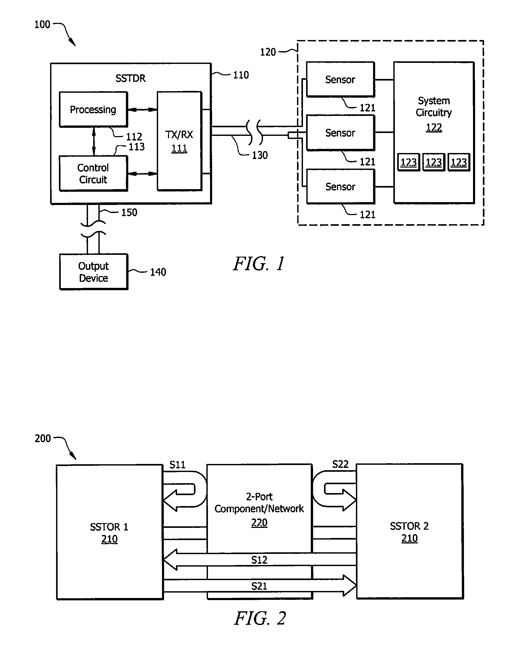
Such multi-port testing may decrease the overall time necessary to run tests with respect to prior methods as two or more ports may be active simultaneously to obtain measurements.

Method used


Image

  • Systems and methods for implementing S/SSTDR measurements
  • Systems and methods for implementing S/SSTDR measurements
  • Systems and methods for implementing S/SSTDR measurements

Examples


Embodiment Construction

Applications of S / SSTDR Measurements

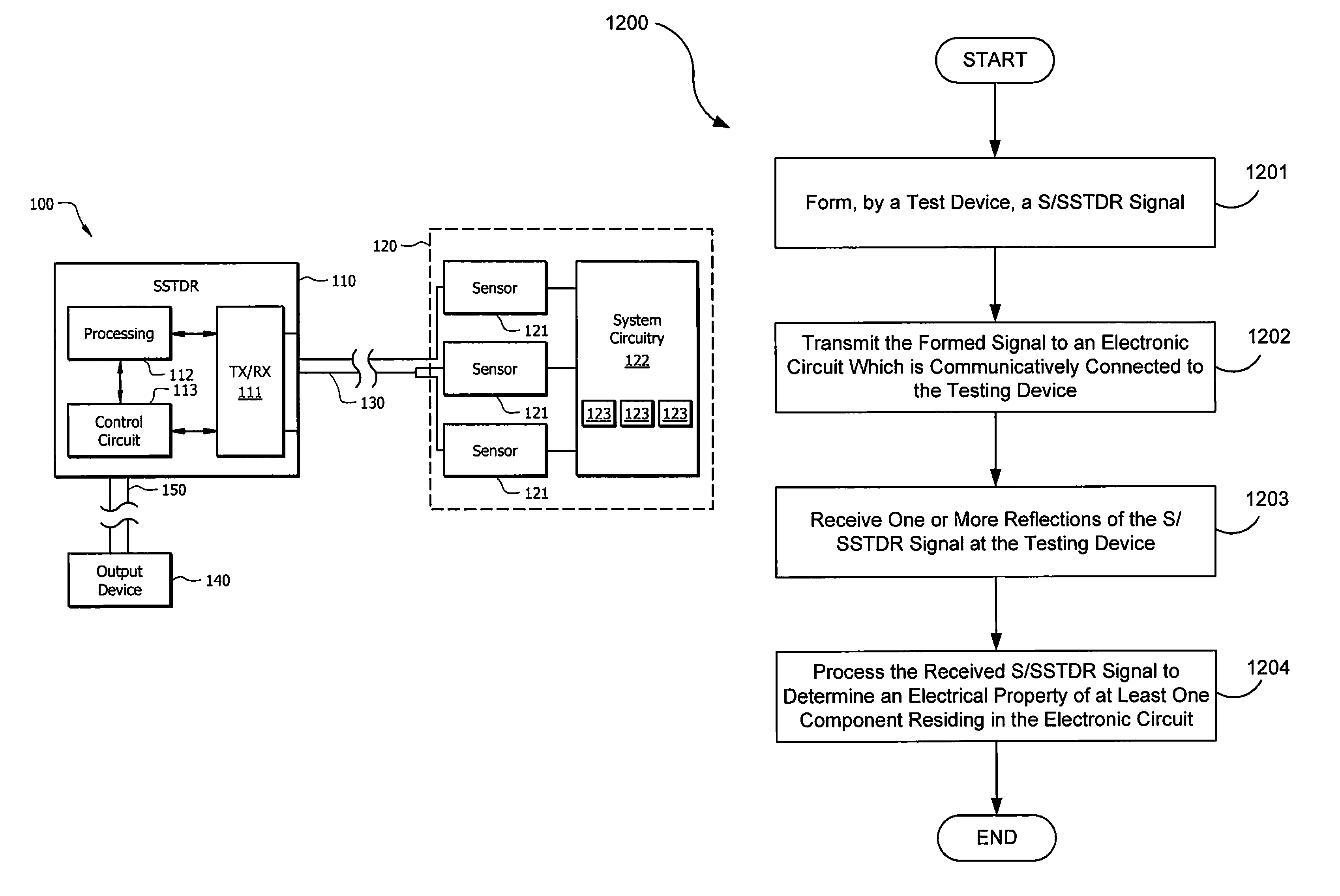
[0034]Spread spectrum sensing is different than electrical test systems used today. In general, spread spectrum sensing methods send a coded high frequency electrical signal down a wire, where it reflects off of impedance changes and returns to the original source. The time delay between the incident and reflected signals tells the distance to the fault (its location). The nature of the reflected signal tells what kind of fault it is. For example, the reflected signal is positive for Open Circuit (OC), and negative for short circuit (SC). Previous systems are generally limited or directed toward taking such measurements.

[0035]Embodiments may utilize similar principles to detect other variations that may be reflected in the coded electrical signal. Such variations may correspond to resistance (R), inductance (L), capacitance (C), and impedance (Z). In practice, variations due to resistance reflect the incident signal with a magnitude proportional t...


PUM


Abstract

Systems and methods which utilize spread spectrum sensing on live circuits to obtain information regarding a circuit under test are provided. In some embodiments S / SSTDR testing may be utilized to obtain R, L, C and Z measurements from circuit components. In yet further embodiments, these measurements may be utilized to monitor the output of sensors on a circuit.

Description

TECHNICAL FIELD[0001]The present application relates to measuring reflected electrical signals to derive information from the reflected signals.BACKGROUND[0002]Since the advent of electrical circuits, systems, and electronic devices various methods have been conceived to test these devices in order to recognize flaws in the electronic circuits and to improve design. Common testing methods may include using a separate tool or meter which a user may utilize to make electrical contact with a circuit in order to measure various properties such as voltage (V), current (I), resistance (R), capacitance (C), inductance (L) or impedance (Z). Such measurements may be useful in many circumstances, e.g. in circuit design, for interrogating sensors which provide data in terms of these measurements, etc.[0003]More recently, time domain reflectometry (TDR) has been used to provide a single-point measurement (transmit / receive at same point) for the reflection from the circuit. With TDR, a step or p...

Claims


Application Information

Patent Timeline
Patent Type & Authority Patents(United States)
IPC IPC(8): G01R31/11G01R31/28G01R27/02
CPCG01R31/2879G01R31/2841G01R27/02G01R27/06G01R31/11G01R31/008
Inventor FURSE, CYNTHIAKHAN, FAISAL
Owner UNIV OF UTAH RES FOUND
Learn More