Systems and methods for maximizing dissolved gas concentration of a single species of gas from a mixture of multiple gases

a technology of a single species and a mixture of multiple gases, applied in the direction of sustainable biological treatment, filtration separation, separation processes, etc., can solve the problems of not being able to optimize water treatment cost and effectiveness, the system is limited to nearly continuous use, and the dissolved ozone concentration of bubble-based technology is limited to much lower dissolved ozone concentration in the water. to achieve the effect of maximizing the concentration of dissolved ozon

Active Publication Date: 2016-02-02
THE BOARD OF TRUSTEES OF THE UNIV OF ARKANSAS +1
View PDF88 Cites 7 Cited by
  • Summary
  • Abstract
  • Description
  • Claims
  • Application Information

AI Technical Summary

Benefits of technology

[0017]Alternately, the gas that is removed from the gas headspace may be provided to processes external to the invention to improve overall process economics by reusing the gas in the headspace. For example, the gas removed from the headspace may be injected into wastewater upstream or downstream of the invention to either ozonate or oxygenate the wastewater being treated.

Problems solved by technology

These conventional systems for dissolving gases in liquids, and in particular conventional dissolved ozone delivery systems, are based on dissolving bubbles into stationary or flowing water and are greatly limited in the range of dissolved ozone concentration that can be attained and controlled.
These conventional systems are also limited to nearly continuous use at constant dissolved ozone concentration, and cannot quickly adjust dissolved ozone concentrations to optimize water treatment cost and effectiveness.
Bubble-based technology is limited to much lower dissolved ozone concentration in the water being treated because of lower pressure and less-efficient gas transfer.

Method used


Image

  • Systems and methods for maximizing dissolved gas concentration of a single species of gas from a mixture of multiple gases
  • Systems and methods for maximizing dissolved gas concentration of a single species of gas from a mixture of multiple gases
  • Systems and methods for maximizing dissolved gas concentration of a single species of gas from a mixture of multiple gases

Examples


Embodiment Construction

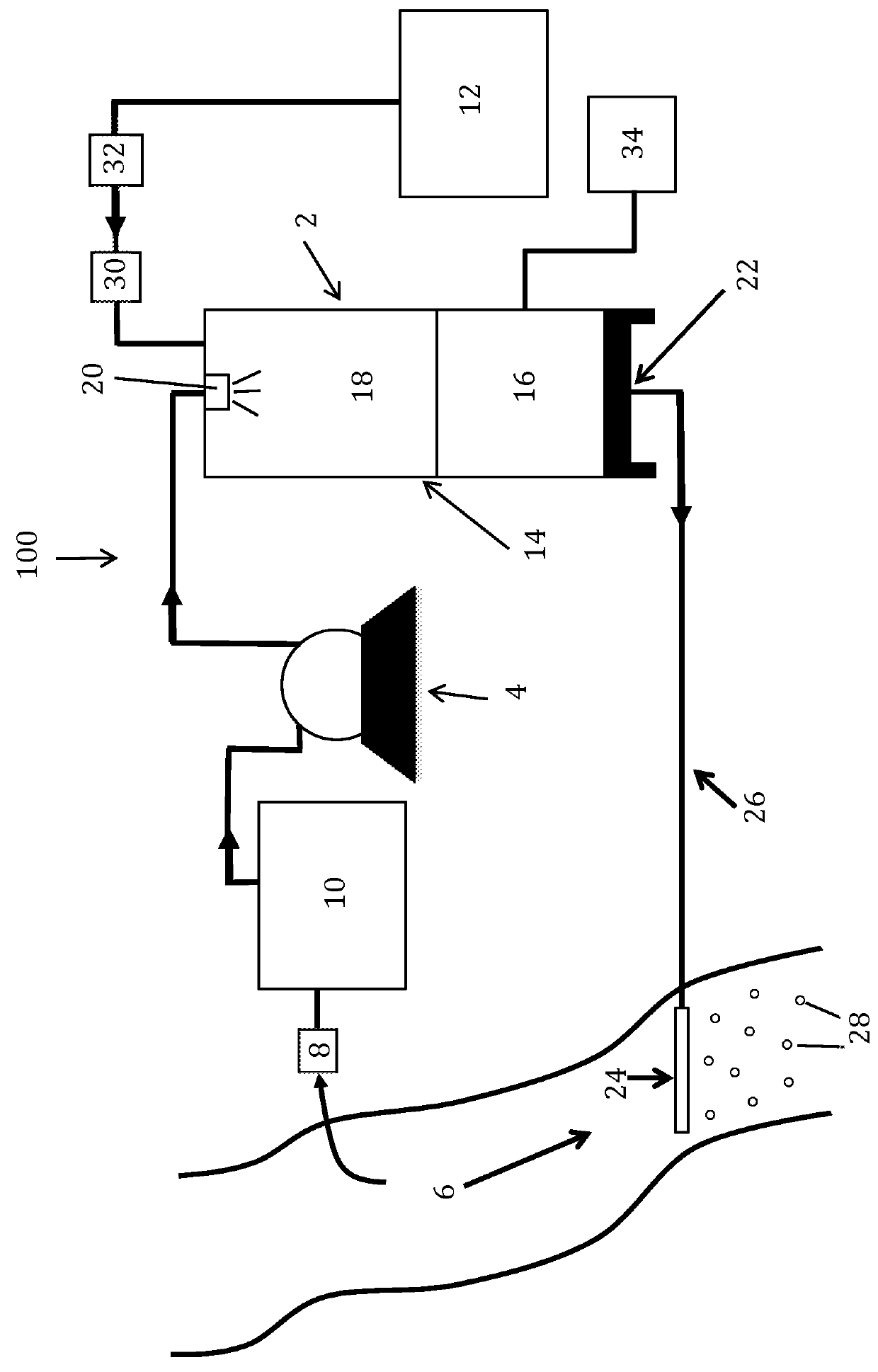
[0036]Disclosed herein are detailed descriptions of specific embodiments of the systems and methods of the present invention for maximizing the concentration of a dissolved gas in a liquid. It will be understood that the disclosed embodiments are merely examples of ways in which certain aspects of the invention can be implemented and do not represent an exhaustive list of all of the ways the invention may be embodied. Indeed, it will be understood that the systems, devices, and methods described herein may be embodied in various and alternative forms. The figures are not necessarily to scale and some features may be exaggerated or minimized to show details of particular components. Well-known components, materials or methods are not necessarily described in great detail in order to avoid obscuring the present disclosure.

[0037]Figures illustrating the components show some elements that are known and will be recognized by one skilled in the art. The detailed descriptions of such eleme...


PUM

PropertyMeasurementUnit
concentrationaaaaaaaaaa
pressureaaaaaaaaaa

Abstract

An apparatus and method for maximizing the dissolved concentration of ozone in a liquid. The apparatus includes a dissolution tank having a pressure vessel configured to contain a treated fluid and at least one gas in a head space above the treated fluid, an inlet configured to permit passage of an untreated fluid into the head space, and an outlet configured to permit passage of the treated fluid out of the vessel; a gas supply system configured to transport the at least one gas to the head space; a fluid supply system configured to provide the untreated fluid to the tank; a bleed-off system for removing gas from the head space so as to maximize the dissolved concentration of the ozone gas in the liquid; and a discharge device configured to pass the treated fluid from the tank into the target liquid.

Description

CROSS-REFERENCE TO RELATED APPLICATIONS[0001]This application is a continuation-in-part application of, and claims the benefit of, U.S. patent application Ser. No. 11 / 921,057, filed Nov. 7, 2008 and issued as U.S. Pat. No. 8,276,888 on Oct. 2, 2012, which is the national stage entry of International Patent Application No. PCT / US2006 / 020391, which claims the benefit of U.S. patent application Ser. No. 11 / 137,856, filed May 25, 2005 and now issued as U.S. Pat. No. 7,255,332, which in turn claims priority to U.S. Provisional Application No. 60 / 574,152, filed on May 25, 2004. This application is also a continuation-in-part application of, and claims the benefit of, U.S. patent application Ser. No. 13 / 415,402, filed Mar. 8, 2012, entitled “System and Method for Optimizing the Dissolution of a Gas in a Liquid,” which in turn claims priority to U.S. Provisional Application No. 61 / 450,364, filed on Mar. 8, 2011. This application also claims the benefit of U.S. Provisional Application No. 61...

Claims


Application Information

Patent Timeline
Patent Type & Authority Patents(United States)
IPC IPC(8): B01F3/04B01F5/04C02F1/78B01F3/08C02F7/00
CPCB01F3/0473B01F3/0876B01F5/0463B01F5/0498C02F1/78C02F7/00B01F2003/04886C02F2209/005C02F2209/02C02F2209/40Y02W10/15Y02W10/10B01F23/234B01F23/237613B01F23/454B01F25/31331B01F25/32
Inventor OSBORN, GREGORY, SCOTT
Owner THE BOARD OF TRUSTEES OF THE UNIV OF ARKANSAS
Why Eureka
Try Eureka