Quick-change attachment configuration for a hole saw

a technology of quick-change attachment and hole saw, which is applied in the direction of chucks, manufacturing tools, transportation and packaging, etc., can solve the problems of user exerting more strength and jeopardizing the cutting process, and achieve the effect of quick replacement and subsequent rotation for actuation

Active Publication Date: 2016-02-02
ROTE MATE IND
View PDF9 Cites 23 Cited by
  • Summary
  • Abstract
  • Description
  • Claims
  • Application Information

AI Technical Summary

Benefits of technology

[0008]With the quick-change attachment means for a hole saw, it is an objective of the present invention to provide a locking switch capable of reducing required applied force and capable of locking and releasing a longitudinal body. Another advantage of the present invention is that it is possible to required less number of mechanical parts for assembly, thereby decreasing construction difficulty which also preserving use safety.
[0009]A main feature of the quick-change attachment means of the present invention is that the quick-change attachment means includes a locking component that can allow the longitudinal body to be slidably released and locked, the quick-change attachment means also includes a positioning component that can keep the quick-change attachment means attached in a predetermined place on the hole saw and disconnect therefrom.
[0010]The locking component of the longitudinal body according to the present invention has the advantage of being intuitive to use, and can release and allow the longitudinal body to slide freely on the quick-change attachment means. In more elaborate terms, the positioning component uses two pins for serving its positioning purpose. Also, the positioning component is installed in the quick-change attachment means to actuatingly fix the quick-change attachment means onto the closed surface of the hole saw. This is enabled because the working condition for the hole saw requires an assembly together with a longitudinal body, and the quick-change attachment means can provide support for coupling the longitudinal body to the hole saw to facilitate subsequent rotation for actuation.
[0011]An objective of the present invention is to offer a method in which the quick-change attachment means, one that can be quickly replaced in the longitudinal body, can be attached and fixed in place on the hole saw, can lock onto the drill bit shank after the longitudinal body passes through the hole of the quick-change attachment means. The longitudinal body can be free to rotate radially while it is axially locked in place. By way of the above mechanism, a longitudinal body can be dislodged from the quick-change attachment means and the hole saw, while shavings emerging from the working terminal of the longitudinal body can be removed at the same time when the longitudinal body is dislodged from the quick-change attachment means and the hole saw. Applicable situations benefiting the above solution include after the hole saw has performed cutting, after the longitudinal body has been unlocked from the quick-change attachment means.
[0012]The quick-change attachment configuration for a hole saw is directed to a tool for use in drilling circular holes on wooden planks. Its constitution includes a hole saw, a longitudinal body and a quick-change attachment means, the hole saw herein includes a threaded aperture, a closed end, and coupling apertures. The longitudinal body is a shank that is capable of accommodating a drill bit, it includes a driving end, a tool end and a limiting portion, wherein the limiting portion cooperates with the quick-change attachment means to securely couple the locking component to the shank.
[0013]An advantage of the present invention is that the quick-change attachment means used for assembling the longitudinal body and the hole saw together comprises a locking component and a positioning component. The locking component comprises a first component and a second component. The first component has an axial hole, an attachment means, a threaded portion, first attachment apertures and positioning apertures. The component has a first central hole, second attachment holes, and first through holes, where an outer diameter of an end of the first central hole is curvilinear.

Problems solved by technology

Disadvantageously, because the latch operates by pressing from top to bottom, and an end of the latch is used as a fulcrum, a problem with the invention is that the user using the tool would have to press down and hold down the latch on another end of the fulcrum.
The applied force holding on these positions may not be necessarily well-distributed, and the disproportional pressing may consequently cause the user to exert more strength than necessary in order to suppress the latch down from becoming subject to axial release.
A problem implicated by this structure is that the actuating of the hole saw and the longitudinal body are both handled by radial rotation, and the adapter is also subject to radial rotation when coupling, therefore it is highly possible that during operation of the driving mechanism, the anti-vibrational force can cause the threaded spots of the quick-change attachment means and the hole saw to unscrew, thereby jeopardizing the cutting process.

Method used


Image

  • Quick-change attachment configuration for a hole saw
  • Quick-change attachment configuration for a hole saw
  • Quick-change attachment configuration for a hole saw

Examples


first embodiment

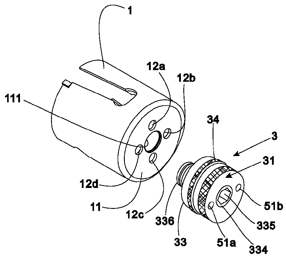
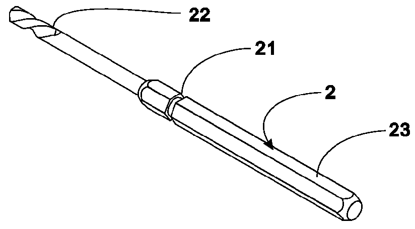
[0033]Referring now to the first embodiment illustrated in FIGS. 1 through 8, the quick-change attachment configuration for a hole saw includes a hole saw 1, a longitudinal body 2 and a quick-change attachment means 3. The hole saw 1 has a threaded aperture 111, a closed surface 11, and coupling apertures 12a, 12b, 12c, 12d. The coupling apertures 12a, 12b, 12c, 12d are each separated with each pair aligned to form a cross on the closed end 11. The threaded aperture 111 is located at the axial center of the closed end 11; further, the longitudinal body 2 is a drill bit shank, which includes a drilling end 23, a tool end 22, and a limiting portion 21, wherein the limiting portion 21 can be used to help the quick-change attachment means 3 fasten the locking component 3′ and ultimately look the movement of the longitudinal body 2.

[0034]More particularly, the quick-change attachment means 3 used for assembling the longitudinal body 2 and the hole saw 1 comprises a locking component 3′ a...

second embodiment

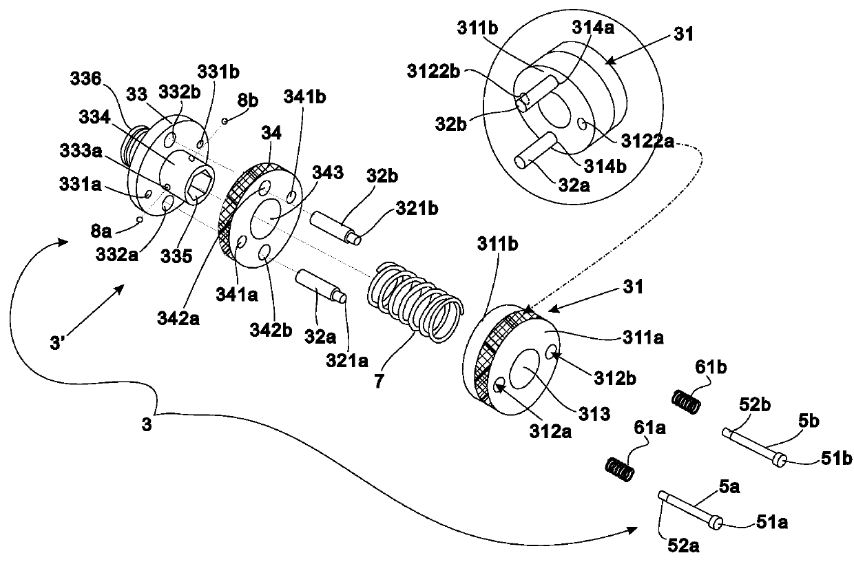
[0045]Next, as shown in FIGS. 9 through 12 which depict the present invention, the quick-change attachment means 3 includes a locking component 3′ and a positioning component 31, wherein the locking component 3′ is the first component 33, the first component 33 has an axial hole 335, an attachment portion 334, a threaded portion 336, a first attachment holes 332a, 332b and positioning apertures 331a, 331b. The positioning component 31 has a second central hole 313, receiving holes 312a, 312b, mortises 314a, 314b, and two locking pins 32a, 32b. The receiving holes 312a, 312b have first openings 3121a, 3121b and second openings 3122a, 3122b. The inner diameters of the second openings 3122a, 3122b are smaller than the inner diameter of the first openings 3121a, 3121b. The width of diameters of the first openings 3121a, 3121b spans from a distance away from ends of the receiving holes 312a, 312b to terminal ends and gradually shrink to form the second openings 3122a, 3122b whose inner d...


PUM

PropertyMeasurementUnit
axial displacementaaaaaaaaaa
inner diameteraaaaaaaaaa
outer diameteraaaaaaaaaa

Abstract

A quick-change attachment configuration is directed to a tool for use with a hole saw for boring holes on a wooden plank, particularly the quick-change attachment configuration is arranged for quickly replacing a longitudinal body, which is a drill bit shank having a driving end, a tool end, and a limiting portion. The configuration includes a quick-change attachment for assembling a longitudinal body and a hole saw which has an axial hole for allowing a longitudinal body to move on the quick-change attachment, and a locking component for locking and releasing the longitudinal body on and from the quick-change attachment. The locking component has a first component and a second component, which when used, the longitudinal body is easily moved slidably and locked so the shreddings emerging from the hole saw are cleaned.

Description

BACKGROUND OF THE INVENTION[0001]1. Fields of the Invention[0002]The present invention is directed to a quick-change attachment means for a hole saw, which is a tool used with a hole saw specifically used for wooden planks. The quick-change attachment means is particularly designed for coupling to a hole saw, in which the locking component and the positioning component in the quick-change attachment means can allow for faster reload of longitudinal body and detachment from the hole saw.[0003]2. Descriptions of Related Art[0004]As with the technology disclosed in Chinese Patent Application No. CN101076420A, entitled “Quick-change and Plug Eject Arbor for a Hole Saw,” the quick-change attachment means used for quickly replacing drill bit shank where the quick-change attachment means can be fitted to the hole saw is coupled to the longitudinal body (which is a drill bit shank), and is locked with respect to the longitudinal body and cannot be free to rotate, and also locked axially. Be...

Claims


Application Information

Patent Timeline
Patent Type & Authority Patents(United States)
IPC IPC(8): B23B51/04B23B31/107
CPCB23B51/0473B23B31/1071B23B51/0426Y10T408/895Y10T408/896Y10T408/8973Y10T408/95
Inventor LAI, YING-TSUNG
Owner ROTE MATE IND
Why Eureka
Try Eureka